Corrosion-resistant dry-grinding-resistant centrifugal pump

A corrosion-resistant, pump casing technology, applied in the field of anti-corrosion centrifugal pump production, can solve the problems of cooling water consumption, cooling water leakage, pump seal failure, etc., to achieve scientific working principle, convenient maintenance and installation, and simple sealing structure Effect

Pending Publication Date: 2020-03-24
宜兴市宙斯泵业有限公司
View PDF2 Cites 3 Cited by
  • Summary
  • Abstract
  • Description
  • Claims
  • Application Information

AI Technical Summary

Problems solved by technology

This kind of pump shaft seal has excellent anti-corrosion performance, and all mechanical seal components will not be corroded by the conveying medium, but there are the following disadvantages: First, the conveying medium in the pump chamber is in contact with the rubber push ring, and the rubber push ring is immersed In the conveyed medium, the acidity or alkalinity in the conveying medium will produce a reduction reaction of the vulcanizing agent on the rubber push ring, which will soften the rubber push ring and lose its elasticity, thereby causing the seal to fail
The third is that the machine seal cannot be equipped with external cooling water, so as long as the pump loses fluid and runs, the machine seal will be burned by dry grinding
Through innovation and improvement, the rubber push ring in the original technology has no contact with the conveying liquid in the pump chamber, and the push ring will not be deformed by the acid and alkali medium in the pump chamber, and the seal can also run empty , has good anti-dry wear performance, but there are still the following problems that are difficult to solve: First, because the cavity between the pump chamber and the sealing box is separated by a flexible partition with a "U"-shaped ring groove, the flexible partition Due to the pressure change of the fluid in the pump chamber, the plate body will be tightened and compressed or pushed away. The dynamic and static rings are disengaged, causing the delivery liquid in the pump cavity to leak into the cooling water cavity, making the pump seal invalid
The second is that the shaft seal 5 that seals the cooling water has a short service life, generally only 3 to 4 months, and there is still a hidden danger of cooling water leakage
The third is that each pump consumes 2~3 tons of cooling water per day, which is very considerable
[0006] Therefore, the mechanical seal of the centrifugal pump with good anti-corrosion performance and the fluid does not contact the metal components of the sealing part in the original technology still has the shortcomings of unstable performance and leakage of cooling water, and there is still a need for improvement.

Method used


Image

  • Corrosion-resistant dry-grinding-resistant centrifugal pump
  • Corrosion-resistant dry-grinding-resistant centrifugal pump
  • Corrosion-resistant dry-grinding-resistant centrifugal pump

Examples


Embodiment 1

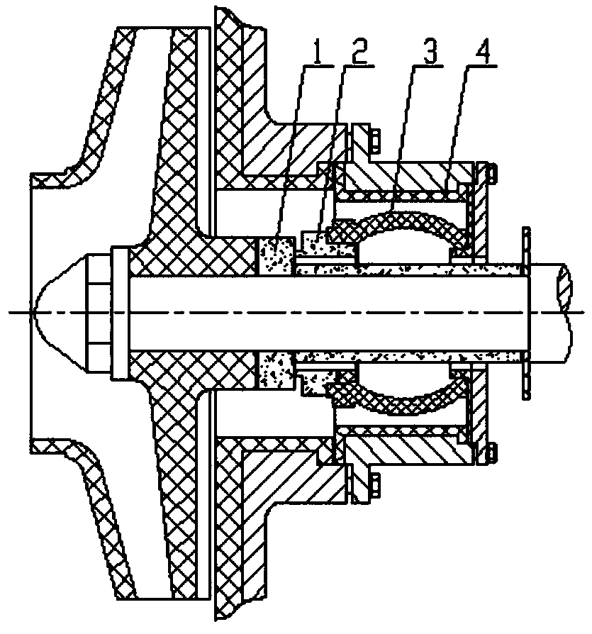
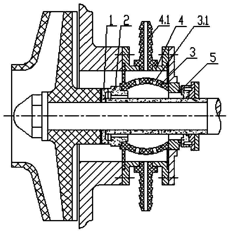
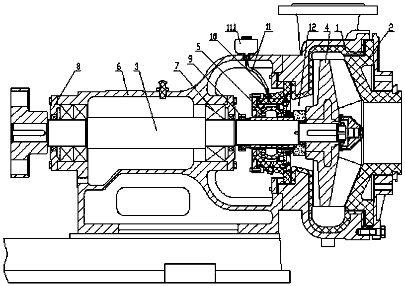
[0043] Embodiment 1: as image 3 , 4 As shown, a corrosion-resistant and anti-dry wear centrifugal pump includes a pump casing 1, a main shaft 3, a shaft seal on the main shaft 3, a bearing seat 6, and an impeller 4 installed at the end of the main shaft 3 and located in the volute cavity of the pump casing 1. The shaft seal includes a seal box assembly and a mechanical seal 5. The mechanical seal 5 includes a static ring 5.2 and a dynamic ring 5.1. The seal box assembly is fixedly connected to the pump casing 1. The shaft sleeve 5.3 is sleeved on the main shaft 3. The dynamic ring 5.1 is clamped and fixed on the Between the shaft sleeve 5.3 and the impeller 4, the moving ring 5.1 is located in the pump cavity and is in contact with the conveying material liquid. The sealing box assembly includes the sealing box 5.5, which is separately connected with the sealing box 5.5. The sealing box presses the rear cover 5.6 and is placed in the sealing box 5.5. The static ring pushes t...

Embodiment 2

[0044] Embodiment 2: as Figure 5 As shown, with reference to Example 1, other features remain unchanged, the static ring pushing elastic ring 5.4 is a straight cylindrical shape with corrugations, and the internal test is provided with a steel compression ring 5.1.3.

Embodiment 3

[0045] Embodiment 3: as Figure 8 As shown, with reference to Embodiment 1, the other features remain unchanged. The end of the shaft sleeve 5.3 near the impeller 4 is provided with a valgus accommodation chamber 5.3.1 for fixing the moving ring 5.1, and the moving ring 5.1 is fixed in the valgus accommodation chamber 5.3.1. The shaft sleeve 5.3 is located on the front side of the sealing box pressure back cover 5.6 and is provided with an anti-rotation and anti-pull-off hole 5.3.3.1 and a groove 5.3.3.2, and a positioning piece 5.1.4 and a positioning screw 5.15 are arranged in the groove 5.3.3.2 The positioning piece 5.1.4 is fixed on the back cover 5.6 of the sealing box, and a fastening screw is arranged in the hole 5.3.3.1 to fix the shaft sleeve 5.3 on the main shaft 3. The concave-convex part 5.3.2 coupled with the moving ring 5.1 is arranged in the eversion accommodation chamber 5.3.1. A sealing member 5.3.4 is provided between the outer peripheral surface of the movi...


PUM


Abstract

The invention discloses a corrosion-resistant dry-grinding-resistant centrifugal pump, which comprises a pump shell, a main shaft, a shaft seal on the main shaft, a bearing seat and an impeller installed at the end of the main shaft and located in a pump shell volute cavity. The shaft seal comprises a sealing box assembly and a mechanical seal. The mechanical seal comprises a static ring and a movable ring; the sealing box assembly is fixedly connected with the pump shell; the movable ring is fixed on the main shaft; the movable ring is positioned in the pump cavity and is in contact with conveyed feed liquid; the sealing box assembly comprises a sealing box, a sealing box pressing rear cover which is separated from or integrated with the sealing box, and a static ring pushing elastic circle arranged in the sealing box; two ends of the static ring pushing elastic circle are compressed between the sealing box pressing rear cover and the static ring; the static ring pushing elastic circle is in an elastic compression state, a static ring friction amplitude and a movable ring friction amplitude are contacted and sealed, a rigid partition plate is fixedly connected to the sealing end face of the sealing box and the sealing end face of the pump shell, the circumferential face of an inner hole of the rigid partition plate makes contact with the outer circumferential face of the static ring in a sealed mode, and the outer circumferential face of the static ring pushing elastic circle, the sealing box pressing rear cover, the rigid partition plate and the static ring form a liquidstorage cavity in a surrounding mode.

Description

technical field [0001] The invention relates to the field of anticorrosion centrifugal pump manufacture, in particular to a centrifugal pump for conveying corrosive slurry containing chlorine ion components and the like. Background technique [0002] Centrifugal pumps are used to transport the clear liquid or slurry containing chloride ions in the flue gas desulfurization process of iron and steel enterprises and coal chemical enterprises, and in the nickel-cobalt hydrometallurgy process. However, this type of medium is very corrosive to metals, especially the pump shaft seal, which requires metal components such as metal springs, bolts and nuts, and these components are easily corroded by the transported chlorine-containing ionic liquid or corrosive gas. It is therefore thought of developing a centrifugal pump with a pump shaft seal in which the liquid does not come into contact with the metal components. [0003] Some people use a lip-shaped rubber seal with a dynamic sea...

Claims


Application Information

Patent Timeline
Patent Type & Authority Applications(China)
IPC IPC(8): F04D7/06F04D29/12
CPCF04D7/06F04D29/126
Inventor 蒋龙福郭丹枫王岩夏鹏飞蒋力峰蒋凌超盛振华
Owner 宜兴市宙斯泵业有限公司
Why Eureka
Try Eureka