
Proton exchange membrane fuel cell stack activation method

A fuel cell stack and proton exchange membrane technology, applied in fuel cells, electrochemical generators, circuits, etc., can solve the problems of reduced membrane electrode activity, increased cost, uneven voltage distribution, etc., to reduce activation time and reduce activation cost , the effect of less energy consumption

Inactive Publication Date: 2020-03-24
浙江高成绿能科技有限公司
View PDF4 Cites 8 Cited by
  • Summary
  • Abstract
  • Description
  • Claims
  • Application Information

AI Technical Summary

Problems solved by technology

At present, the commonly used fuel cell activation methods include electrolytic activation method and constant current natural activation method. The electrolytic activation method is likely to cause problems such as uneven voltage distribution, non-parallel activation effects, and reduced membrane electrode activity; the constant current natural activation method needs to consume a large amount of hydrogen and Additional humidification device, which increases the cost and requires a longer activation time, usually more than 4 hours

Method used


Image

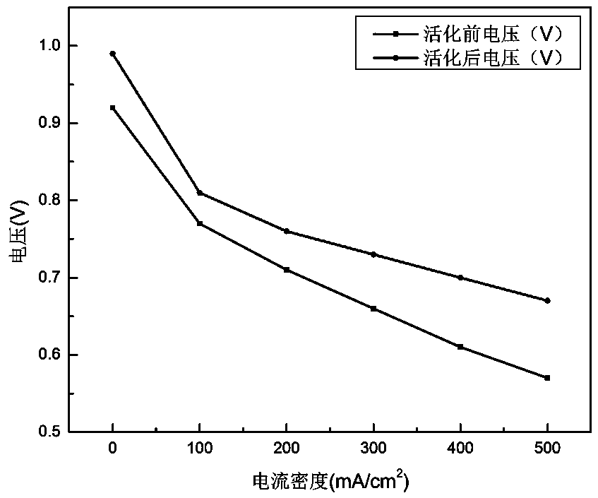
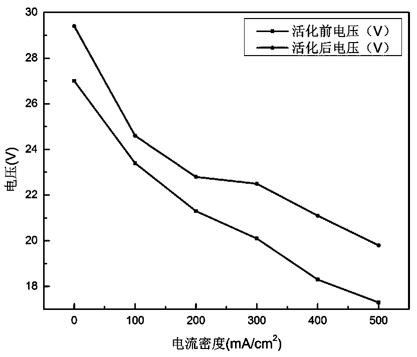
  • Proton exchange membrane fuel cell stack activation method
  • Proton exchange membrane fuel cell stack activation method

Examples


Embodiment 1

[0037] Embodiment 1 of the present invention provides a method for activating a proton exchange membrane fuel cell stack, comprising the following steps:

[0038] Step one, check the airtightness of the proton exchange membrane fuel cell stack;

[0039] Step 2: Introduce hydrogen into the anode of the single-piece proton exchange membrane fuel cell stack, and the hydrogen flow rate is 5000 mlmin -1 , the hydrogen pressure is 4 Kpa, the cathode is fed with low-flow air, the electronic load is adjusted to constant voltage mode, and the voltage of the proton exchange membrane fuel cell stack is gradually reduced in the single-chip 0.5V mode until the single-chip voltage is close to 0.2V, and Keep for 5 minutes;

[0040] Step 3, after turning off the electronic load, air-cool the proton exchange membrane fuel cell stack;

[0041] Step 4, repeat steps 2 and 3 5 times, then turn off the electronic load, and the anode stops air intake;

[0042] Step 5: Introduce hot water at 60°C ...

Embodiment 2

[0045] Embodiment 2 of the present invention provides a method for activating a proton exchange membrane fuel cell stack, comprising the following steps:

[0046] Step one, check the airtightness of the proton exchange membrane fuel cell stack;

[0047] Step 2: Introduce hydrogen into the anodes of 30 proton exchange membrane fuel cell stacks, and the hydrogen flow rate is 5000 mlmin -1 , the hydrogen pressure is 30 Kpa, the cathode is fed with low-flow air, the electronic load is adjusted to constant voltage mode, and the voltage of the proton exchange membrane fuel cell stack is gradually reduced in the single-chip 0.5V mode until the single-chip voltage is close to 0.2V, and Hold for 8 minutes;

[0048] Step 3, after turning off the electronic load, air-cool the proton exchange membrane fuel cell stack;

[0049] Step 4, repeat steps 2 and 3 5 times, then turn off the electronic load, and the anode stops air intake;

[0050] Step 5: Introduce hot water at 60°C at the anod...


PUM


Abstract

The invention discloses an activation method of a proton exchange membrane fuel cell stack. The activation method comprises the following steps: step 1, checking the air tightness of the proton exchange membrane fuel cell stack; step 2, introducing hydrogen into the anode of the proton exchange membrane fuel cell stack, introducing air into the cathode of the proton exchange membrane fuel cell stack, gradually reducing the voltage of the proton exchange membrane fuel cell stack in a constant-voltage mode, and keeping the voltage for 5-10 minutes; 3, cooling the proton exchange membrane fuel cell stack; step 4, repeating the step 2 and the step 3 for 3-5 times, and then stopping air intake of the anode; and 5, introducing hot water into the anode of the proton exchange membrane fuel cell stack until the performance of the proton exchange membrane fuel cell stack is stable. According to the activation method of the proton exchange membrane fuel cell stack provided by the invention, the activation cost is remarkably reduced, and the whole activation process can be completed within about 1 hour.

Description

technical field [0001] The invention relates to the technical field of fuel cells, [0002] In particular, the present invention relates to a method for activating a proton exchange membrane fuel cell stack. Background technique [0003] A proton exchange membrane fuel cell (PEMFC) is a power generation device that directly converts the chemical energy stored in fuel into electrical energy without combustion. PEMFC is mainly composed of a bipolar plate, a porous mass transfer layer and a membrane electrode. The membrane electrode is composed of a proton exchange membrane and an electrode coated with a catalyst on both sides. The outside of the electrode is a gas diffusion layer. A single cell is formed by clamping the membrane electrode with a graphite plate or metal plate with a flow channel. A sealing ring is provided between the graphite plate and the gas diffusion layer to ensure the airtightness of the battery. The fuel cell stack is assembled by stacking multiple sin...

Claims


Application Information

Patent Timeline
Patent Type & Authority Applications(China)
IPC IPC(8): H01M8/04223H01M8/04701H01M8/04858
CPCH01M8/04223H01M8/04701H01M8/0488Y02E60/50
Inventor 侯向理裴昱李叶涛姚宇希
Owner 浙江高成绿能科技有限公司
Learn More