Light load detection and power tube partial conduction control method and circuit

A conduction control circuit, conduction control technology, applied in control/regulation systems, output power conversion devices, DC power input conversion to DC power output, etc. Problems such as poor load regulation rate, to achieve the effect of suppressing the output voltage floating, reducing the output voltage drop, and reducing the output voltage

Pending Publication Date: 2020-03-24
SHENZHEN NANYUN MICROELECTRONICS CO LTD
View PDF5 Cites 0 Cited by
  • Summary
  • Abstract
  • Description
  • Claims
  • Application Information

AI Technical Summary

Problems solved by technology

[0023] At present, the common isolation transformer drive controller chips on the market have relatively poor load regulation, such as TI (Texas Instruments) chips SN6501 and SN6505, Maxim (Maxim Semiconductor) chips MAX256, MAX258, etc., according to their specifications. It is not difficult to find that the load regulation rate is 10

Method used


Image

  • Light load detection and power tube partial conduction control method and circuit
  • Light load detection and power tube partial conduction control method and circuit
  • Light load detection and power tube partial conduction control method and circuit

Examples


no. 1 example

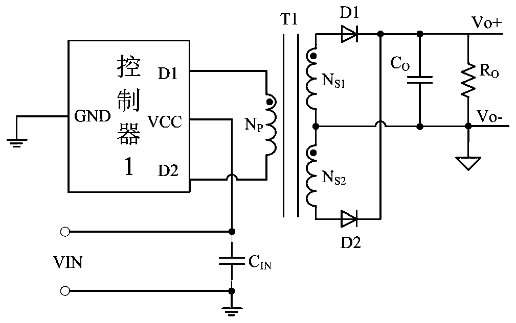
[0086] like Figure 4 Shown is a schematic circuit diagram of the application of the controller applying the light load detection and power tube partial conduction control circuit of the present invention to the driver of the full bridge converter. like Figure 4 As shown, the GND port of the controller 100 is connected to the ground, the D1 port is connected to the drains of the power transistors PM1_m, PM1_n, NM1_m, and NM1_n inside the controller 100, and connected to the drains of the winding N P Similarly, the D2 port is internally connected to the drains of the power transistors PM2_m, PM2_n and NM2_m, NM2_n, and externally connected to the winding N P The other end of the connection, the input filter capacitor C IN It is connected between the voltage input terminal VCC of the controller 100 and the ground to filter the input voltage VIN, and the anodes of the output rectifier diodes D1 and D2 are respectively connected to the two terminals of the secondary coil Ns1 an...

no. 2 example

[0122] The circuit principle diagram of the light load detection and power tube partial conduction control circuit in the controller 200 of the second embodiment of the present invention and Figure 5 The same, so no repeated drawing.

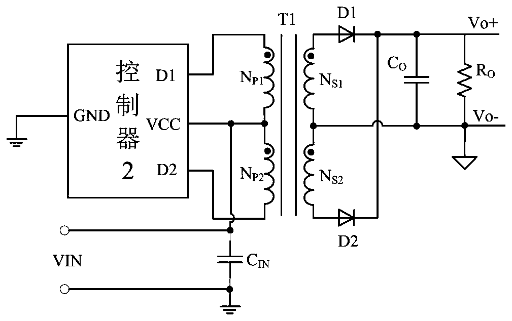
[0123] like Figure 17 Shown is a schematic circuit diagram of a push-pull driver application of a controller applying the light load detection and power tube partial conduction control circuit of the present invention. The difference from Embodiment 1 is that the VCC port of the controller 200 and the coupling transformer T1 Primary coil N p1 and N p2 The center tap connection of the controller 200, the D1 port is connected with the drains of the power transistors NM1_m and NM1_n inside the controller 200, the D2 port controller 200 is connected with the drains of the power transistors NM2_m and NM2_n, and its D1 and D2 ports are respectively connected with the coupling transformer T1 The primary coil N p1 and N p2 The two ends of the con...

Embodiment 2

[0127] The specific circuit principles and beneficial effects of the second embodiment are the same as those of the first embodiment, and will not be repeated here.

[0128] The above are only preferred embodiments of the present invention. It should be noted that the above-mentioned preferred embodiments should not be considered as limiting the present invention, and it should also be recognized that the present invention can be applied in other wider scopes. In addition, the present invention It is also applicable to a DC-DC isolation converter with only one power tube, but the power tube unit at this time outputs a power tube drain voltage signal. Compared with the first embodiment, the voltage detection unit needs to reduce one channel, due to the number of power tubes If it is reduced, the number of driving signal paths that the driving control unit needs to generate will also be correspondingly reduced. According to the above content of the present invention, using commo...


PUM


Abstract

The invention provides a light load detection and power tube partial conduction control method and circuit. The method is applied to an occasion where multiple power tubes are connected in parallel for use, and comprises the following steps: a voltage detection step: detecting a drain voltage when the power tubes are conducted, comparing a drain voltage signal with a voltage detection threshold with a return difference, and outputting a comparison result signal; a drive control step of generating a drive signal according to the comparison result signal output in the voltage detection step, andperforming control of full conduction or partial conduction of the power tube; and a power tube output step: controlling the conduction of the power tube according to the driving signal output in thedriving control step, and outputting the drain voltage of the power tube. According to the invention, the drain voltage of the power tube is detected, and when the converter is in a light load state,part of the power tube is turned off, so that the conduction internal resistance of the power tube is increased, the output voltage of the converter is reduced, the output voltage difference betweenthe light load and the heavy load is reduced, and the load adjustment rate is improved.

Description

technical field [0001] The invention relates to the technical field of DC-DC isolation converters, in particular to a method and circuit for light load detection and partial conduction control of power tubes, and is especially suitable for isolation transformer drivers. Background technique [0002] At present, most of the isolated transformer drivers on the market adopt push-pull topology or full-bridge topology. The circuit structure is simple, the transformer is excited bidirectionally during operation, and the utilization rate of the magnetic core is high. The advantages of good dynamic response are widely used in low-voltage input, high-current output, and occasions where electrical isolation is required for input and output. [0003] figure 1 The circuit shown is a common full-bridge converter in the prior art, which adopts a full-bridge circuit structure, the GND port of the controller 1 is connected to the ground, and its D1 port is internally connected to one side ...

Claims


Application Information

Patent Timeline
IPC IPC(8): H02M3/335H02M1/08
CPCH02M3/33523H02M1/08H02M1/0035Y02B70/10
Inventor 赵志伟温镓俊
Owner SHENZHEN NANYUN MICROELECTRONICS CO LTD
Why Eureka
Try Eureka