Tail gas treatment device

A tail gas treatment and nitrogen technology, which is applied in gas treatment, dispersed particle separation, membrane technology, etc., can solve the problems of backflow of tail gas, unstable negative pressure of epitaxial furnace, and blockage of tail gas treatment device, so as to reduce maintenance cost and extend maintenance cycle Long, avoid clogging effect

Inactive Publication Date: 2020-03-27
XIAN ESWIN MATERIAL TECH CO LTD +1
View PDF8 Cites 2 Cited by
  • Summary
  • Abstract
  • Description
  • Claims
  • Application Information

AI Technical Summary

Problems solved by technology

[0004] During tail gas treatment, trichlorosilane reacts with water to undergo hydrolysis, producing hydrogen, silicon dioxide, hydrogen chloride and a large amount of heat. Among them, silicon dioxide is easy to agglomerate and block the tail gas treatment device, resulting in unstable negative pressure of the epitaxy furnace
When the exhaust gas treatment device cannot provide a stable negative pressure for the epitaxial path, there may be a risk of exhaust gas backflow, which may easily cause the epitaxial furnace cavity to be polluted by metal and particles, seriously affecting the output

Method used


Image

  • Tail gas treatment device
  • Tail gas treatment device
  • Tail gas treatment device

Examples


Embodiment 1

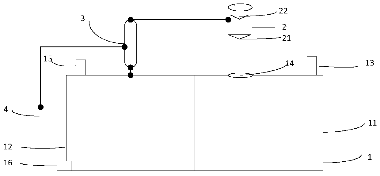
[0062] A tail gas treatment device, specifically as figure 1 shown, including:

[0063] A water tank (1), the water tank (1) is divided into a negative pressure chamber (11) and a normal pressure chamber (12), and water is stored in the negative pressure chamber (11) and the normal pressure chamber (12);

[0064] The negative pressure chamber (11) is provided with an air inlet (13) and a channel (14);

[0065] One spray tower (2), the top of described spray tower (2) is provided with water spray outlet (21) and lye spray outlet (22), the bottom of described spray tower (2) and described The passage (14) of the negative pressure chamber (11) is connected, and the passage is used to input gas into the spray tower, and the solid impurities in the spray tower are discharged into the negative pressure chamber;

[0066] The atmospheric chamber (12) is provided with an air outlet (15) at the top and a drain (16) at the bottom;

[0067] The normal pressure chamber (12) is connected...

Embodiment 2

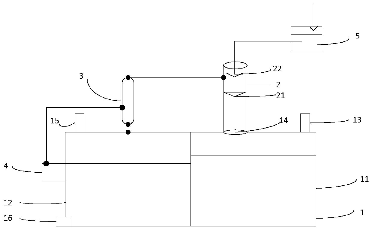
[0070] A tail gas treatment device, specifically as figure 2 shown, including:

[0071] A water tank (1), the water tank (1) is divided into a negative pressure chamber (11) and a normal pressure chamber (12), and water is stored in the negative pressure chamber (11) and the normal pressure chamber (12);

[0072] The negative pressure chamber (11) is provided with an air inlet (13) and a channel (14);

[0073] One spray tower (2), the top of described spray tower (2) is provided with water spray outlet (21) and lye spray outlet (22), the bottom of described spray tower (2) and described The passage (14) of the negative pressure chamber (11) is connected, and the passage is used to input gas into the spray tower, and the solid impurities in the spray tower are discharged into the negative pressure chamber;

[0074] The lye supply unit (5) is connected with the lye spray port (22) at the top of the spray tower;

[0075] The lye supply unit includes an lye storage unit and a ...

Embodiment 3

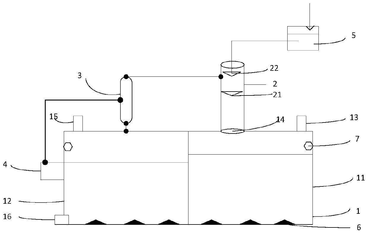
[0080] A tail gas treatment device, specifically as image 3 shown, including:

[0081] A water tank (1), the water tank (1) is divided into a negative pressure chamber (11) and a normal pressure chamber (12), and water is stored in the negative pressure chamber (11) and the normal pressure chamber (12);

[0082] The negative pressure chamber (11) is provided with an air inlet (13) and a channel (14);

[0083] One spray tower (2), the top of described spray tower (2) is provided with water spray outlet (21) and lye spray outlet (22), the bottom of described spray tower (2) and described The passage (14) of the negative pressure chamber (11) is connected, and the passage is used to input gas into the spray tower, and the solid impurities in the spray tower are discharged into the negative pressure chamber;

[0084] The atmospheric chamber (12) is provided with an air outlet (15) at the top and a drain (16) at the bottom;

[0085] The normal pressure chamber (12) is connected...


PUM


Abstract

The invention relates to the field of semiconductor production, in particular to a tail gas treatment device. The tail gas treatment device comprises a water tank which is divided into a negative pressure cavity and a normal pressure cavity, and the negative pressure cavity is provided with an air inlet and a channel; a spray tower internally provided with a water spray port and an alkali liquor spray port, wherein the bottom of the spray tower is connected with the channel of the negative pressure cavity, an air outlet is formed in the top of the normal pressure cavity, a water outlet is formed in the bottom of the normal pressure cavity, the normal pressure cavity is connected with the spray tower through a venturi tube, and the venturi tube is used for conveying gas in the spray tower to the normal pressure cavity and exhausting the gas from the air outlet; and a variable-frequency fan used for conveying water in the normal pressure cavity into the venturi tube to form negative pressure. The tail gas treatment device is good in tail gas treatment effect, not prone to causing blockage and long in maintenance period, and the maintenance cost is reduced.

Description

technical field [0001] The invention relates to the field of semiconductor production, in particular to a tail gas treatment device. Background technique [0002] The epitaxial growth process is a method of depositing a single crystal thin film on the surface of a single crystal substrate. When preparing the epitaxial film of silicon, the silicon source material is used as the raw material and deposited on the substrate. After epitaxial growth, the tail gas produced includes silicon source gases such as trichlorosilane that have not participated in the reaction, and hydrogen chloride gas. [0003] Since silicon source gases such as trichlorosilane and hydrogen chloride gas are highly dangerous, they cannot be directly discharged or exposed to the air, and must be treated by an exhaust gas treatment device before being discharged. [0004] During tail gas treatment, trichlorosilane undergoes a hydrolysis reaction with water, producing hydrogen, silicon dioxide, hydrogen chl...

Claims


Application Information

Patent Timeline
Patent Type & Authority Applications(China)
IPC IPC(8): B01D53/78B01D53/68
CPCB01D53/68B01D53/78B01D2257/55B01D2258/0216
Inventor 方圭哲金柱炫其他发明人请求不公开姓名
Owner XIAN ESWIN MATERIAL TECH CO LTD
Why Eureka
Try Eureka