
Ash removal device before plating for cylinder body electroplating

A pre-plating and cylinder technology, which is applied in the direction of jewelry, etc., can solve the problems of scratching the workpiece, high equipment capacity requirements, non-professionals cannot operate, etc., and achieve the effect of increasing the overall strength, simple and compact structure, and compact structure layout

Active Publication Date: 2021-03-02
LONCIN MOTOR
View PDF9 Cites 0 Cited by
  • Summary
  • Abstract
  • Description
  • Claims
  • Application Information

AI Technical Summary

Problems solved by technology

The existing dynamic electroplating pre-plating deashing generally adopts ultrasonic ash removal, which can be applied to almost all ash-hanging materials encountered at present, and can achieve perfect ash removal effect under the premise of sufficient ultrasonic power , but the equipment capacity requirements are high. Even if the domestic ordinary ultrasonic vibration heads are fully arranged at the bottom and surrounding of the tank, it is difficult to achieve 100W / L power. If you want to meet the requirements, you must use ultrasonic transducer rods to directly connect the energy source It is possible to achieve this power requirement in the local space of the cylinder bore only if it is placed inside the cylinder bore; however, under the same power requirements, domestic ultrasonic transducers are often too thick in diameter to be placed in the cylinder bore, or even if they can be placed , and the gap is too small, it is easy to collide with the workpiece on the hanging basket
Imported ultrasonic transducers are expensive
The main thing is that since the energy emission of the ultrasonic source is also a sinusoidal waveform, it will form a strong and weak ash removal effect on the inner wall of the cylinder bore. In severe cases, "zebra patterns" will appear. Reversed, so the requirements for equipment manufacturing and control are high; and the structure of placing the transducer rod in the cylinder is less versatile, especially when switching between double cylinder products, due to different hole center distances, it must be accurate Adjust the position of the transducer
It must be adjusted once after switching, and non-professionals cannot operate it. If the position is adjusted incorrectly, the workpiece will be scratched, or a crash will occur, causing serious damage to the production line.

Method used


Image

  • Ash removal device before plating for cylinder body electroplating
  • Ash removal device before plating for cylinder body electroplating
  • Ash removal device before plating for cylinder body electroplating

Examples


Embodiment Construction

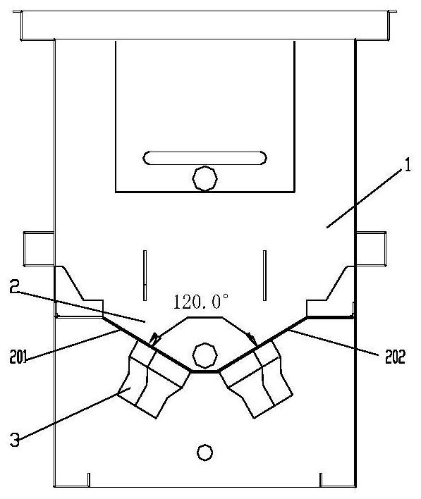
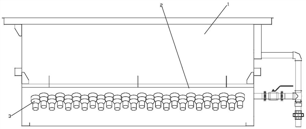
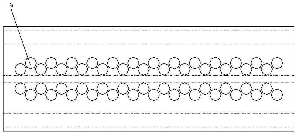
[0022] figure 1 It is a structural sectional view of the present invention, figure 2 for figure 1 Side view (remove one side of the tank wall), image 3 It is the expanded view of the V-shaped groove of the present invention, Figure 4 For the tooling diagram (with workpiece) matched with the present invention, as shown in the figure: the pre-plating ash removal device for cylinder electroplating of the present embodiment includes ash removal tank 1 and an ultrasonic generating assembly, and the ultrasonic generating assembly Including a transducing head 3 (vibrating head) and a driver (for driving the transducing head to generate ultrasonic waves, which belongs to the prior art and will not be described in detail here), the transducing head 3 is located on the lower outer side of the ash removal tank 1 , and the oblique setting makes the ultrasonic generation direction (referring to the main generation direction of the transducing head, which can be understood as the cent...


PUM

PropertyMeasurementUnit
angleaaaaaaaaaa
widthaaaaaaaaaa
angleaaaaaaaaaa

Abstract

The invention discloses a pre-plating ash removal device for cylinder body electroplating, which includes an ash removal tank and an ultrasonic generating assembly. The ultrasonic generating assembly includes a transducer head and a driver. The oblique setting makes the direction of the ultrasonic generation face the ash removal tank for the range of the inner hole of the workpiece after the workpiece is placed; the invention avoids the use of chemical ash removal methods and meets environmental protection requirements; at the same time, it abandons the prior art and puts the transducer rod into the workpiece The structure of the hole adopts an oblique displacement head, and the ultrasonic wave directly acts on the inner hole of the workpiece (the ash removal tank is on the top), which can meet the ash removal requirements of most cylinders before plating; through the cooperation with the supporting tooling of the workpiece, There is no need to stop the production line, just replace different workpieces and install them directly on the present invention. Therefore, it is suitable for existing workpieces of various sizes, realizes "seamless switching" of products, avoids production loss caused by line shutdown, and quickly meets delivery requirements , to minimize the switching time of mature products and minimize the loss of production capacity.

Description

technical field [0001] The invention relates to a cylinder body electroplating device component, in particular to a pre-plating ash removal device used for cylinder body electroplating. Background technique [0002] As the main part of the engine, plunger pump, reciprocating compressor and other equipment, the cylinder block is used to form the working space together with the piston and the cylinder head; taking the engine as an example, it forms the combustion chamber and provides the movement track for the piston assembly, thus forming power conversion environment. When the cylinder guides the piston to reciprocate continuously, the inner wall of the cylinder and the piston rub against each other for a long time and at high frequency, which reduces the useful power of the cylinder and consumes part of the energy. In order to solve the above problems, electroplating is adopted on the inner wall, and the electroplating coating is used to replace the cylinder liner to solve ...

Claims


Application Information

Patent Timeline
Patent Type & Authority Patents(China)
IPC IPC(8): C25D5/34C25D7/00
CPCC25D5/34C25D7/00
Inventor 聂进何军贺超文家勇
Owner LONCIN MOTOR
Learn More