
Suspension gap visual detection method based on image processing

An image processing and visual inspection technology, applied in the field of magnetic levitation technology and image processing, can solve the problems of measurement accuracy, surface roughness, susceptibility to interference, and high cost.

Active Publication Date: 2020-03-27
成都凯磁科技有限公司
View PDF10 Cites 8 Cited by
  • Summary
  • Abstract
  • Description
  • Claims
  • Application Information

AI Technical Summary

Problems solved by technology

Eddy current sensors are widely used in suspension measurement systems, but there are still many shortcomings and deficiencies. For example, the measurement accuracy is greatly affected by temperature and the surface roughness of the measured object, and temperature compensation and nonlinear correction are required, and the cost is high. The output value of the sensor needs to undergo A / D conversion before it can be connected to the control system
The photoelectric sensor measures the displacement of the object according to how much the measured object blocks the luminous flux. The biggest disadvantage is that it is susceptible to interference and has poor environmental adaptability.

Method used


Image

  • Suspension gap visual detection method based on image processing
  • Suspension gap visual detection method based on image processing
  • Suspension gap visual detection method based on image processing

Examples


Embodiment Construction

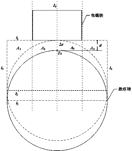
[0050] The present invention will be described in further detail below in conjunction with the accompanying drawings and specific embodiments. The present invention collects high-definition images of the suspension gap area in real time through a high-speed industrial camera, and calculates the pixel area of ​​the area of ​​interest in the suspension gap to obtain the corresponding actual suspension gap distance according to the binarized image of the area of ​​interest in the suspension gap after image processing. High-precision measurement of suspension clearance.

[0051] In order to reduce the difficulty of post-image processing and further improve the accuracy of gap measurement, this embodiment requires the selection of foreground objects and backgrounds with color contrast to make the contrast between the measurement background and foreground objects more prominent, while ensuring that the electromagnets and background objects in the foreground objects The levitation ba...


PUM


Abstract

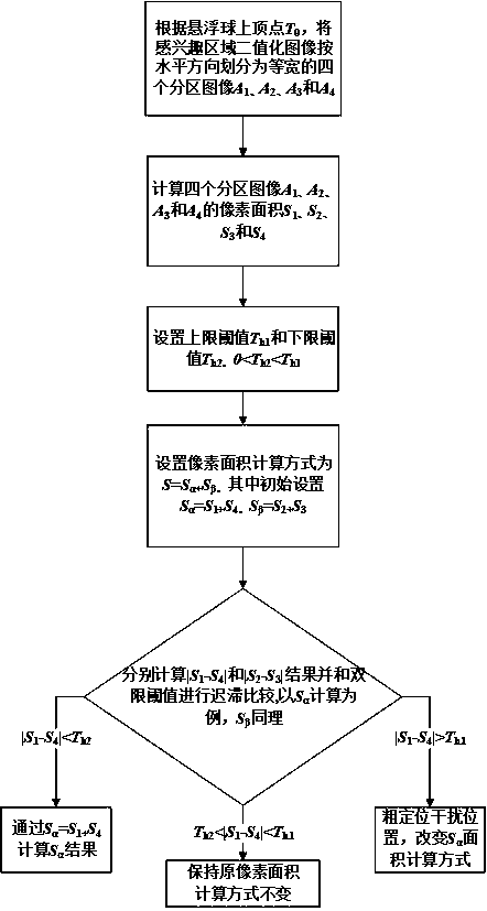
The invention discloses a suspension gap visual detection method based on image processing. The suspension gap visual detection method comprises the steps: firstly obtaining an original high-definition image of a suspension gap region, and processing the original high-definition image to obtain a binary image of a suspension gap region of interest; calculating the number of pixel points with a binarization result of 1 in the binarized image of the suspension gap region of interest to obtain the pixel area s of the suspension gap region of interest; and finally, calibrating the pixel area s andthe actual gap distance, and calculating the actual gap distance d. According to the suspension gap visual detection method, the actual gap distance is calculated according to the image pixel area ofthe region of interest of the suspension gap, and the measurement precision is high, and the anti-interference capability is high, and asymmetric interference existing in the region of interest of the suspension gap can be effectively removed, and meanwhile an interference fault position is alarmed and positioned; and the actual suspension gap distance change is calculated through the image pixelarea change of the region of interest of the suspension gap, and the tracking is sensitive, and the linearity is high, and both the real-time performance and the accuracy can meet the requirements ofa suspension ball control system.

Description

technical field [0001] The invention relates to the fields of magnetic levitation technology and image processing technology, in particular to a high-precision visual detection method for a levitation gap based on image processing. Background technique [0002] The suspension gap signal detection is an important part of the closed-loop control of the magnetic suspension system. The magnetic suspension system adjusts the electromagnetic force through the real-time feedback of the gap signal so that the controlled object can overcome the gravity and stabilize at the equilibrium position. The accuracy and real-time performance of levitation gap signal detection directly affect the control performance of the maglev system. In the magnetic levitation ball system, the levitation gap actually refers to the distance from the upper apex of the levitated steel ball to the lower surface of the electromagnet, so the gap sensor is essentially a displacement sensor. [0003] Common displ...

Claims


Application Information

Patent Timeline
IPC IPC(8): G06T7/00G06T7/136G06T7/187G01B11/14
CPCG01B11/14G06T7/0002G06T7/136G06T7/187G06T2207/10004G06T2207/10024G06T2207/20028G06T2207/20132G06T7/11G06T7/70
Inventor 靖永志孔杰郝建华钱程张昆仑
Owner 成都凯磁科技有限公司
Learn More