Method and electrolytic tool for integral blisk integrated electrolytic machining

A technology of integral blisk and processing method, which is applied in electric machining equipment, electrochemical machining equipment, manufacturing tools, etc., to achieve the effects of reducing stray corrosion, improving processing localization, and improving processing efficiency

Active Publication Date: 2020-08-18
HEFEI UNIV OF TECH
View PDF8 Cites 0 Cited by
  • Summary
  • Abstract
  • Description
  • Claims
  • Application Information

AI Technical Summary

Problems solved by technology

However, the above electrolytic machining methods all have the most prominent common problem: since the blade surface of the new integral component is a complex free-form surface in space, the existing integral component electrolytic machining method cannot obtain high-precision complex shape through one-time processing in principle. integral component

Method used


Image

  • Method and electrolytic tool for integral blisk integrated electrolytic machining
  • Method and electrolytic tool for integral blisk integrated electrolytic machining
  • Method and electrolytic tool for integral blisk integrated electrolytic machining

Examples


Embodiment 1

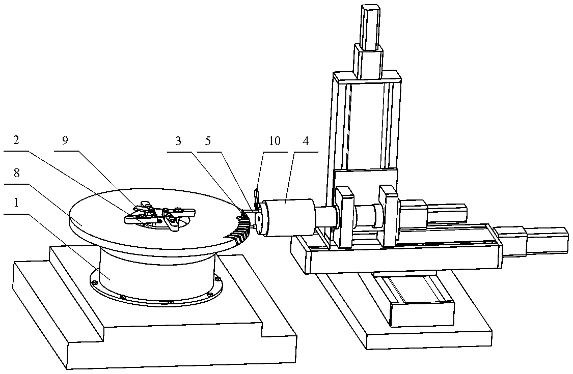
[0050] The workpiece to be processed is an integral blisk of radial blades, with a diameter of 600mm, a thickness of 40mm, the number of blades is 69, and the material is titanium alloy; the cascade channel is narrow, and the blade surface is twisted and easily deformed; the processing accuracy is high, and the blade surface accuracy requires 0.1-0.5mm, the surface roughness of the hub is required to be less than 1.0μm, and the surface roughness of the cascade channel is required to be less than or equal to 1.6μm.

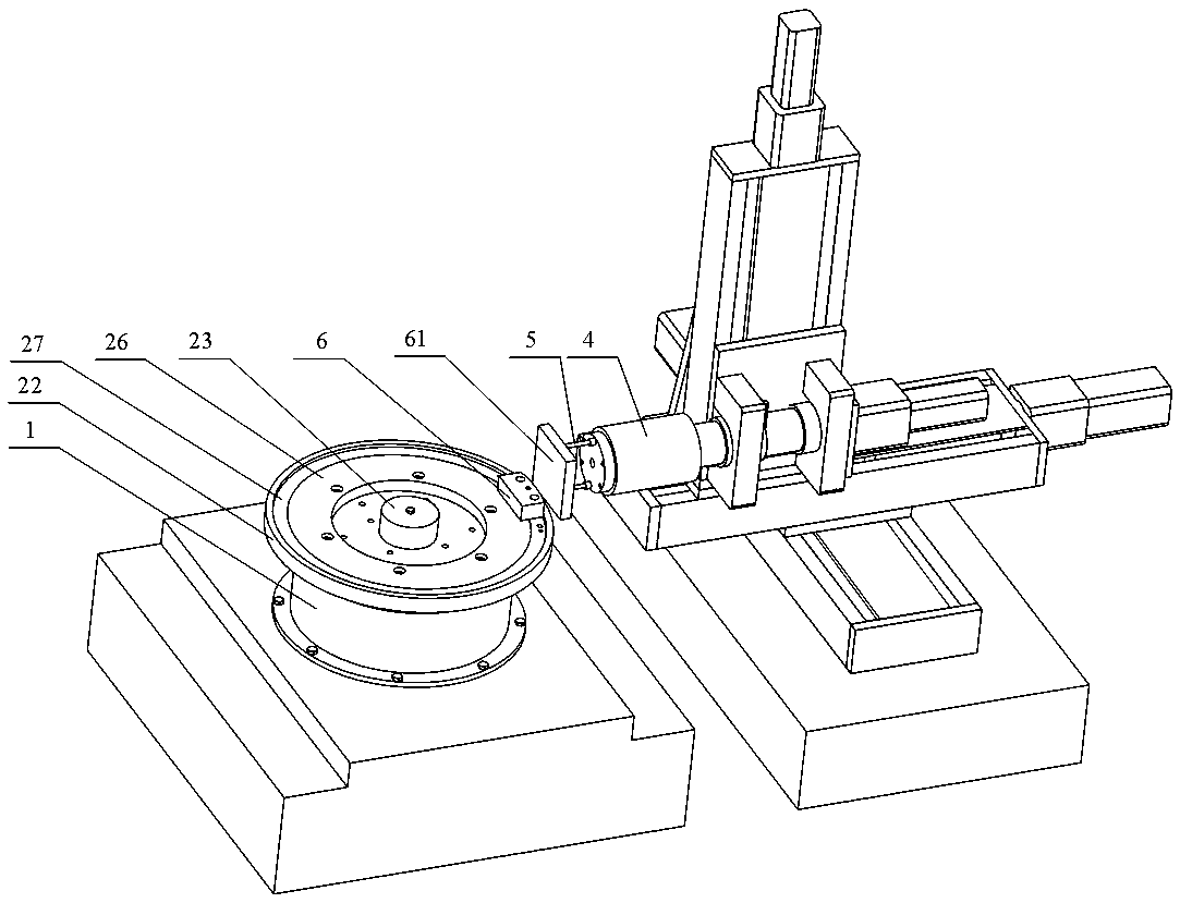
[0051] see figure 1 and image 3 The processing equipment includes a rotary table 1, a workpiece fixture 2 installed on the rotary table, a cathode body 3 located at the passage of the workpiece cascade, a processing spindle of the feed mechanism 4, a connecting rod 5 connecting the curved cathode and the processing spindle, and Tool setting block 6.

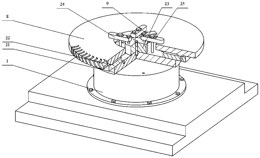
[0052] see figure 2 , The workpiece fixture for electrolytic machining includes an insulating mounting plate ...

Embodiment 2

[0073] see Figure 7 , the workpiece to be processed is an integral blisk of axial blades, with a diameter of 450 mm, a thickness of 30 mm, the number of blades is 90, and the material is superalloy; the accuracy of the blade surface is required to be less than 0.5 mm, and the surface roughness of the cascade channel is required to be Ra less than or equal to 1.6 μm .

[0074] The rotary table is a horizontal structure,

[0075] The specific electrolytic machining operation steps are as follows:

[0076] (1) Tool setting

[0077] Install the workpiece pallet on the horizontal rotary table 1, install the tool setting block 6 on the workpiece pallet; install the electrolytic tool setting block 61 on the front end of the processing spindle of the feed mechanism 4; implement the rotary table 1 and the feed mechanism 4. For the tool setting of the spindle, remove the tool setting block and the electrolytic tool setting block after the tool setting is completed.

[0078] (2) Ins...


PUM

PropertyMeasurementUnit
diameteraaaaaaaaaa
thicknessaaaaaaaaaa
surface roughnessaaaaaaaaaa

Abstract

The invention discloses a tool for achieving integrated electrolysis machining of a complex profile blisk, a blade basin, a blade back and a hub by means of multi-axis linkage of a curved cathode, andrelates to the technical field of electrolytic machining. The tool comprises a rotary workbench, a workpiece clamp mounted on the rotary workbench, a cathode body located at workpiece grid channels,a feeding mechanism capable of performing multi-axis action, a connecting rod for connecting the curved cathode with a machining main shaft and a tool-setting block. The cathode body is of a hollow thin-wall structure, and the geometry of the cathode body is designed according to the grid channels and the hub profile. During machining, the rotary workbench drives a workpiece to do rotary action, the machining main shaft of the feeding mechanism drives the cathode body to move, rotate and the like to form multi-axis linkage, and a blisk workpiece with a complex twisted shape is obtained. The machining method has wide applicability, and the blisk workpiece with high dimensional precision and high surface quality for an aerospace engine can be obtained through one-time machining.

Description

technical field [0001] The invention belongs to the technical field of electrolytic machining, and in particular relates to a method for integral electrolytic machining of a blisk and an electrolytic tool. Background technique [0002] As the core component of the aircraft, the performance of the aero-engine will directly affect the overall performance of the aircraft. The blisk is one of the indispensable parts of the aero-engine. The blades of the traditional blisk are connected with the disc through mortise and mortise. Its structure is complex and its life is short, which is difficult to meet the development of the advanced aviation industry. Integral blisks combine blades and discs as a whole, which overcomes the above disadvantages and also has high working efficiency and thrust-to-weight ratio. However, due to the use of difficult-to-machine materials, complex profiles, and high machining accuracy requirements, the machining and manufacturing of blisks has become a w...

Claims


Application Information

Patent Timeline
Patent Type & Authority Patents(China)
IPC IPC(8): B23H3/00B23H11/00
CPCB23H3/00B23H11/00B23H11/003
Inventor 张聚臣李兴林陈远龙张斌
Owner HEFEI UNIV OF TECH
Why Eureka
Try Eureka