Automobile brake system high-speed switch valve development test method

A technology for automotive braking systems and high-speed switching valves. It is applied in mechanical valve testing, circuit breaker testing, and by measuring fluid growth and deceleration rates. It can solve problems such as high labor intensity, lack of testing procedures, and reduced testing efficiency. Achieve the effects of improving pressure control accuracy, reducing product noise, and reducing testing costs

Pending Publication Date: 2020-03-31
ZHEJIANG ASIA PACIFIC MECHANICAL & ELECTRONICS
View PDF0 Cites 6 Cited by
  • Summary
  • Abstract
  • Description
  • Claims
  • Application Information

AI Technical Summary

Problems solved by technology

[0007] 1. Use the air pressure detection system in the high-speed switch valve production line for testing, but in actual use, the test medium flowing through the high-speed switch valve is brake fluid; due to the different characteristics of gas and liquid as test media, it is difficult for the air pressure detection system to simulate The performance of the high-speed switching valve in the actual hydraulic environment greatly reduces the reliability of the test data;
[0008] 2. Rivet the high-speed switch valve to be verified into the HCU (hydraulic control unit) assembly, and then conduct the test on a professional HCU test system; due to the difference in test requirements between a si...

Method used


Image

  • Automobile brake system high-speed switch valve development test method
  • Automobile brake system high-speed switch valve development test method
  • Automobile brake system high-speed switch valve development test method

Examples


Embodiment 1

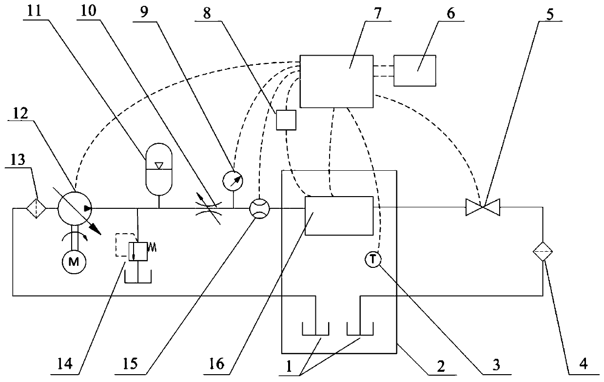
[0099] Embodiment 1: sealing self-test method, such as Figure 7 shown, including the following steps:

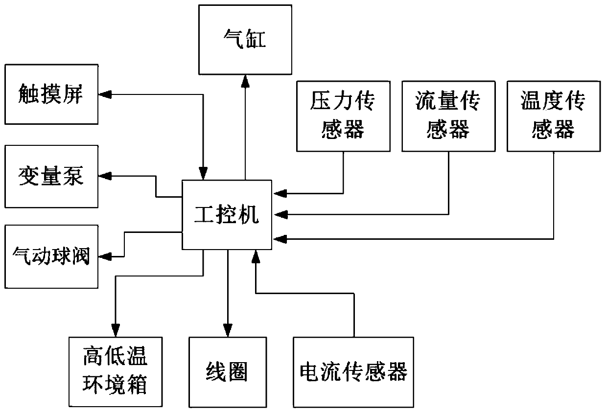
[0100] S001. Preset the pipeline tightness holding time Tp, the valve port sealing time Tv and the allowable pressure drop ΔPp within the pipeline sealing time Tp and the valve sealing time Tv through the touch screen 6 Allowable pressure drop ΔPv, and set tightness test pressure Ps;

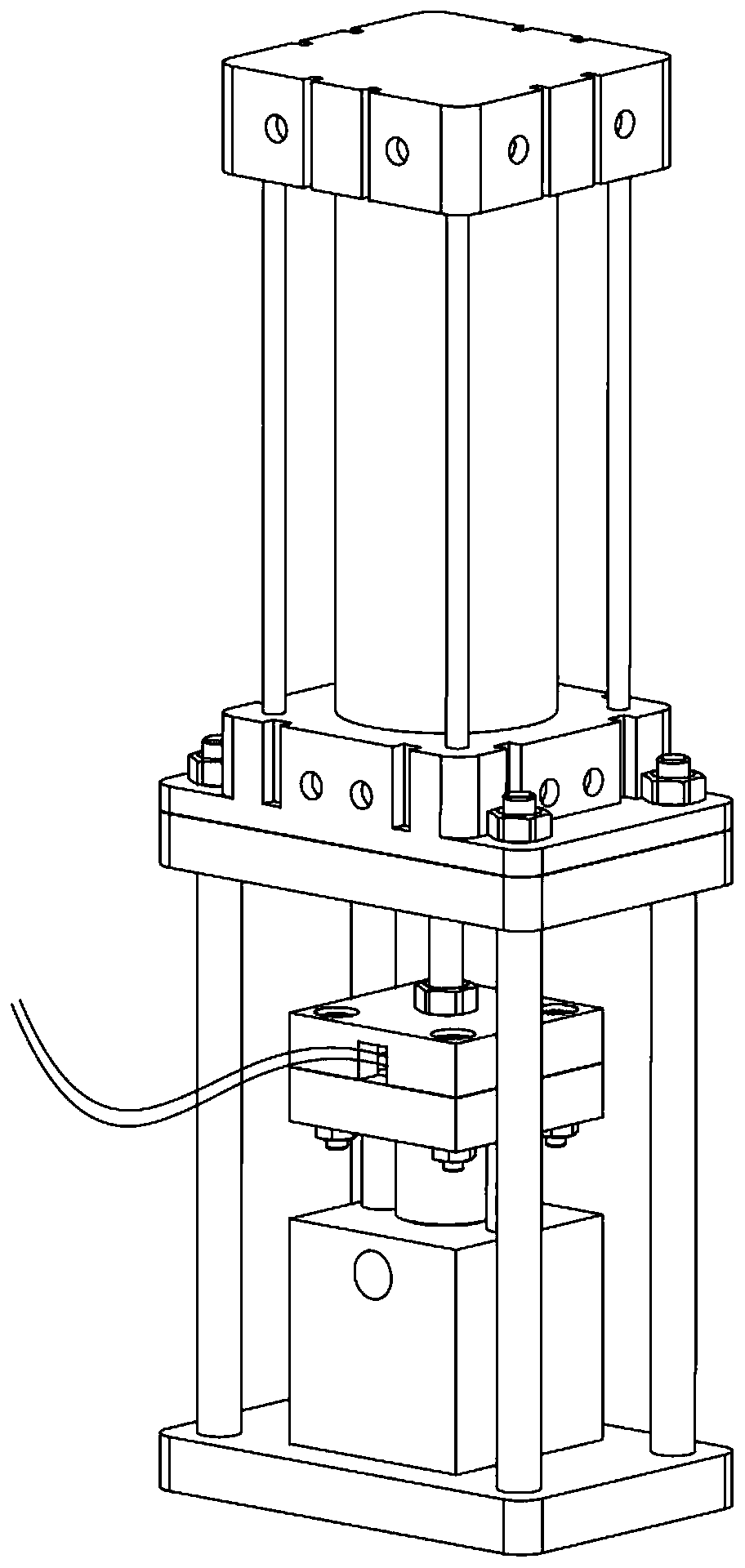
[0101] S002. Control the cylinder shaft 32 of the cylinder 23 to protrude downward through the control box 7, drive the upper pressure plate 27 to press the high-speed switch valve 29, control the closing of the pneumatic ball valve 5 through the control box 7, and establish a pipeline sealing test circuit;

[0102] S003, start the variable pump 12 through the control box 7, and close the variable pump 12 through the control box 7 after the pressure increases to Ps, record the value P1 of the pressure sensor 15 at this time, and start timing;

[0103] S004, record the value P2 of the pressu...

Embodiment 2

[0111] Embodiment 2: proportional flow test method, such as Figure 8 shown, including the following steps:

[0112] S020, set the ambient temperature Tg inside the high and low temperature environmental chamber 2, the valve inlet pressure Pg tested by the pressure sensor, the PWM frequency Fg, the initial value of the PWM duty ratio Dg0, the end value of the PWM duty ratio Dgn, and the value of a single test cycle through the touch screen. Coil energization duration Tgon, coil power-off duration Tgoff of a single test cycle, incremental duty cycle tolerance K of each test cycle, initial value of the number of tests i=1, total number of tests N;

[0113] The outlet of the valve is connected to the oil tank, and the outlet pressure of the valve is atmospheric pressure Pout (0.1MPa). The difference between the inlet and outlet pressure of the valve in this group of tests is the pressure difference of the valve port to be measured (Pg-Pout). In the actual vehicle ECU software cont...

Embodiment 3

[0121] Embodiment 3: proportional pressure test method, such as Figure 9 shown, including the following steps:

[0122] S030, set the ambient temperature Ty, the variable pump pressure Py, the PWM frequency Fy, the initial value of the PWM duty cycle value Dy0, the end value of the PWM duty cycle value Dyn, the coil energization time of a single test cycle Tyon, and The duration of coil power-off and power-on Tyoff for a single test cycle, the incremental duty cycle tolerance K of each test cycle, the initial value of the number of tests i=1, and the total number of tests N;

[0123] S031, the high and low temperature environment box 2 adjusts the temperature in the box to the ambient temperature Tg, and collects the temperature in the box through the temperature sensor 3;

[0124] S032, control the cylinder shaft 32 to extend through the control box 7, the upper pressing plate 27 presses the coil support, and the coil support presses the high-speed switching valve 29 to est...


PUM


Abstract

The invention discloses an automobile brake system high-speed switch valve development test method. A test tool of a high-speed switch valve, an oil tank and a temperature sensor are fixedly installedin a high-low temperature environment box. The oil tank is connected with an inlet of the variable pump through the inlet filter; an outlet of the variable pump is connected with an inlet of the testtool through a throttle valve; an overflow valve and an energy accumulator are connected and installed on a pipeline between the throttle valve and the outlet of the variable pump, a pressure sensorand a flow sensor are connected and installed on a pipeline between inlets of the throttle valve testing tools, and an outlet of each testing tool is connected back to the oil tank after sequentiallypassing through a pneumatic ball valve and an outlet filter. The flexibility of development and test of the high-speed switch valve is improved, the test range is widened, and the test cost is reduced; the testing method is simple, feasible, small in debugging workload and high in testing efficiency, provides data reference for algorithm development of an electro-hydraulic control system, and hasimportant significance in improving pressure control precision and reducing product noise.

Description

technical field [0001] The invention relates to a component development and testing method in the technical field of development and testing of an automobile braking system, in particular, a development and testing method for a high-speed switching valve of an automobile braking system is designed. Background technique [0002] In recent years, with the continuous development of active safety technology, electro-hydraulic control braking systems (such as ABS, ESC, EHB, etc.) have been widely used in automobile braking systems. Because of its simple structure and low cost, the high-speed switching valve has become one of the core components of the electro-hydraulic brake control system. In the past, high-speed on-off valves used low-frequency PWM control, and the flow through the valve port was adjusted by frequent opening and closing of the valve core. This pressure control method is simple, but the accuracy is not high; and the valve core is frequently opened and closed. A...

Claims


Application Information

Patent Timeline
IPC IPC(8): G01M13/003G01M3/28G01R31/327
CPCG01M3/28G01R31/327G01M13/003
Inventor 黄朕张杰秦志勇郑利水郝江脉刘菁晗
Owner ZHEJIANG ASIA PACIFIC MECHANICAL & ELECTRONICS
Why Eureka
Try Eureka