Ultra-fine grinding device for powder coating

A grinding device and powder coating technology, applied in grain processing and other directions, can solve the problems of cumbersome steps, fixed grinding gap, increased production cost, etc., to achieve extremely fine and uniform particle size, ensure uniformity, and excellent grinding effect. Effect

Inactive Publication Date: 2020-04-03
含山县领创新材料科技有限公司
View PDF1 Cites 16 Cited by
  • Summary
  • Abstract
  • Description
  • Claims
  • Application Information

AI Technical Summary

Problems solved by technology

[0004] The technical problem to be solved by the present invention is to design a powder coating ultra-fine grinding device to solve the problem of cumbersome steps and increased production costs caused by the need for coarse grinding and fine grinding when the grinding gap is fixed when the existing powder coating is ground. lack of

Method used


Image

  • Ultra-fine grinding device for powder coating
  • Ultra-fine grinding device for powder coating
  • Ultra-fine grinding device for powder coating

Examples


Embodiment 1

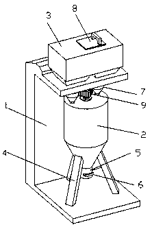
[0033] Embodiment 1 specifically introduces a kind of powder coating ultra-fine grinding device, as attached Figure 1~6 As shown, the main structure includes a fixed frame 1, a grinding cylinder 2 and a storage bin 3, and three legs 4 are arranged at the lower end of the grinding cylinder 2, and the legs 4 are welded to the bottom of the fixed frame 1, and at the bottom of the grinding cylinder 2 A discharge pipe 5 is connected, and a pull-out baffle 6 is arranged on the discharge pipe 5 . Its storage bin 3 is arranged on the top of the fixed frame 1, and the left and right ends of the lower surface of the storage bin 3 are connected with a feed hopper 7, and its feed hopper 7 is connected with the upper surface of the grinding cylinder 2, and the There is a transparent observation window (not shown in the figure) on the warehouse 3, and a feeding port is provided at its upper end, and a cover plate 8 is arranged on the feeding port, and the amount of raw materials inside the...

Embodiment 2

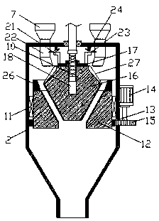
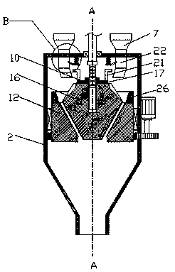
[0039] Embodiment 2 is to make further improvements on the basis of Embodiment 1, and its main improvements are as attached Figure 7~9 As shown, a filter screen 28 is rotated below the rotating ring-shaped grinding block 12, and a fixed block 29 is welded on the inner wall of the grinding cylinder 2 below the filter screen 28, and the fixed block 29 is connected with the screen frame of the filter screen 28. The vibrating spring 30 is connected to the lower end of the movable round table grinding block 16. When the movable round table grinding block 16 moves downward under the action of the reciprocating screw rod 10 and the sliding sleeve 17, the resisting rod 31 touches the filter screen One end of 28 makes screen pack 28 incline. And on the grinding cylinder 2 below filter screen 28 inclined ends, be connected with coarse particle passage 32, be provided with auger conveyer 33 on the outer surface of grinding cylinder 2, its auger conveyer 33 vertically upwards arrange, it...


PUM


Abstract

The invention relates to the technical field of coating grinding millers, in particular to an ultra-fine grinding device for powder coating. The ultra-fine grinding device comprises a fixing frame, agrinding cylinder and a storage bin. The lower end of the grinding cylinder is provided with supporting legs, the supporting legs are connected with the bottom of the fixing frame in a welded manner,the storage bin is arranged at the top end of the fixing frame, the left and right ends of the lower surface of the storage bin are connected with feed hoppers, the feed hoppers communicate with the upper surface of the grinding cylinder, a reduction motor is fixed to the lower surface at the top end of the fixing frame, and an output shaft of the reduction motor penetrates through the lower end at the center of the upper surface of the storage bin to be connected with a reciprocating lead screw. According to the ultra-fine grinding device for the powder coating, the reciprocating lead screw is driven by the reduction motor to rotate so as to realize the up-and-down movement of a movable round table grinding block, and the grinding gap is gradually reduced in the grinding process, so thatextremely fine grinding of the powder coating is realized, and the grinding effect of the ultra-fine grinding device for powder coating is excellent.

Description

technical field [0001] The invention relates to the technical field of paint grinding machines, in particular to a powder paint ultrafine grinding device. Background technique [0002] Powder coating is a solid powder synthetic resin coating composed of solid resin and pigments, fillers and additives. The processing steps of the powder coating include mixing and stirring, melting and extrusion, tableting and solidification, grinding and crushing and other processes. The grinding of powder coating is a crucial step to determine its properties during use. If the powder coating particles are coarse, the surface of the coating will be uneven. Therefore, the existing production process needs to divide the grinding of powder coating into coarse grinding and fine grinding. proceed in two steps. [0003] The patent No. CN108160274B discloses a powder grinding device for producing water-soluble paint, including a processing barrel and a circulating barrel. The processing barrel is ...

Claims


Application Information

Patent Timeline
Patent Type & Authority Applications(China)
IPC IPC(8): B02C2/10B02C23/02B02C23/08B02C23/00
CPCB02C2/10B02C23/00B02C23/02B02C23/08
Inventor 郭平
Owner 含山县领创新材料科技有限公司
Why Eureka
Try Eureka