
Near-net forming method for thin-wall complex component

A near-net-shape, thin-walled technology, applied in the near-net-shape field of thin-walled and complex components, can solve the problems of poor overall rigidity, uneven processing, and difficult processing.

Active Publication Date: 2020-04-03
AVIC BEIJING INST OF AERONAUTICAL MATERIALS
View PDF14 Cites 2 Cited by
  • Summary
  • Abstract
  • Description
  • Claims
  • Application Information

AI Technical Summary

Problems solved by technology

[0003] For structural materials used in high temperature applications such as titanium and nickel, it is difficult to process, and the material loss and long cycle of processing and production will increase the production cost of parts; and for complex parts with special shapes and thin walls, due to poor overall rigidity, processing is easy to cause Uneven deformation, therefore, net shape and near-net shape are the most effective means for forming parts of this type of material

Method used


Image

  • Near-net forming method for thin-wall complex component
  • Near-net forming method for thin-wall complex component

Examples


Embodiment 1

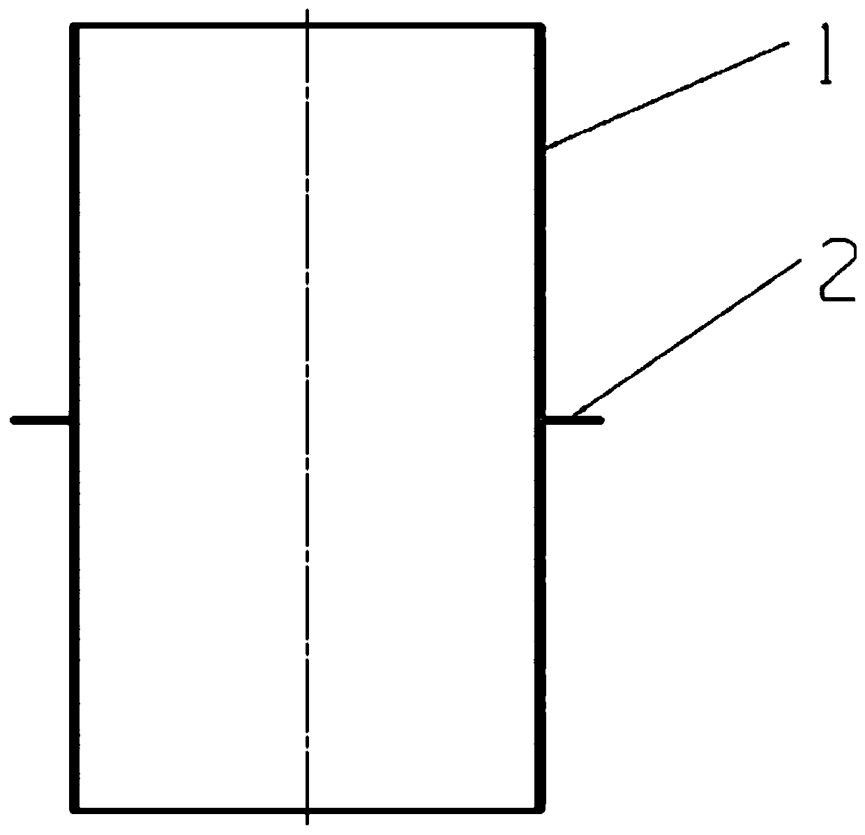
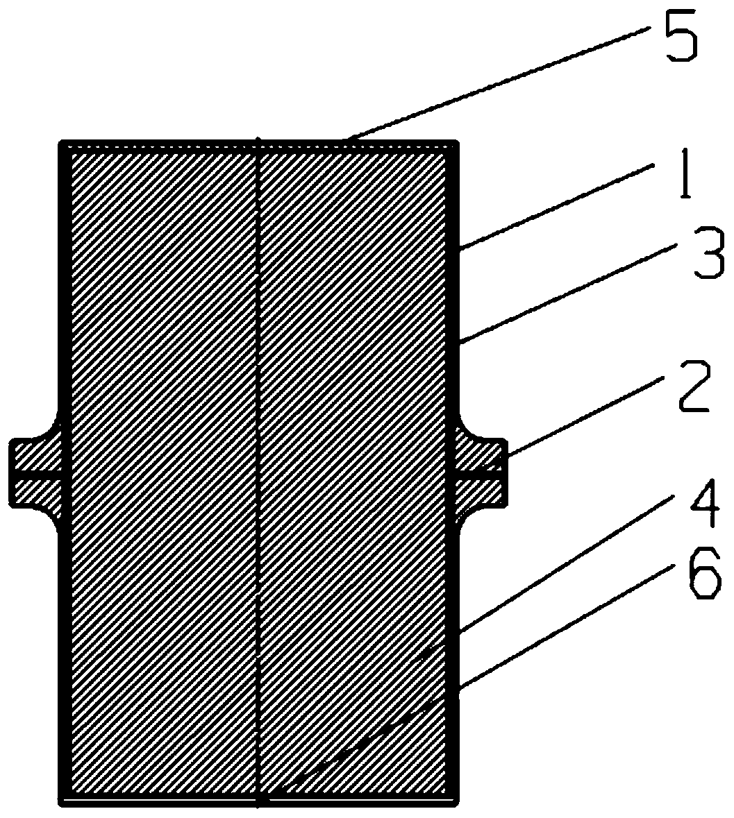
[0017] See attached figure 1 As shown, the processed product of this embodiment is an air inlet, and the material is this TC4 titanium alloy. The maximum size of the plate 2 in the width direction is 300 mm, the wall thickness is 2 mm, and the length is 610 mm. There are 3 thin-wall ribs 1 in total, which are evenly distributed along the length direction outside the wall plate 1. The maximum outer diameter of the annular thin-wall rib 1 is 360 mm, and the thickness is 1.5 mm. mm, thin-walled rib plate 1 and wall plate 2 require integral molding.

[0018] Adopt the method of the present invention to carry out the step of near net shaping to this member as follows:

[0019] 1. Package preparation

[0020] According to the structure of the target part, design and process the carbon steel sheath. The sheath consists of four parts: the cylinder body 3, the mold core 4, the upper end cover 5, and the lower end cover 6. Among them, the cylinder body 4 is a half structure, see the a...

Embodiment 2

[0035] The processed product of this embodiment is an air inlet, which is in a cylindrical state and is composed of irregular cylindrical wall panels and outer ribs. The wall panel material is TiAl alloy, with a maximum dimension of 400 mm in the width direction and a wall thickness of 3 mm. The length is 1500mm, the material of the rib plate is GH4169 high temperature alloy, and it is in the shape of a ring, with a total of 5 lines, which are uniformly distributed along the outer axis of the wall plate. The outer diameter of the ring is 360mm, the thickness is 2mm, and the inner side coincides with the outer side of the wall plate.

[0036] Adopt the method of the present invention to carry out the step of near net shaping to this member as follows:

[0037] 1. Package preparation

[0038] According to the structure of the target part, design and process the carbon steel sheath, which consists of four parts: cylinder body 3, mold core 4, upper end cap 5, and lower end cap 6, ...


PUM

PropertyMeasurementUnit
Thicknessaaaaaaaaaa
Average particle sizeaaaaaaaaaa
Surface roughnessaaaaaaaaaa

Abstract

The invention relates to a near-net forming method for a thin-wall complex component. According to the method, a metal sheath designed through a special structure is utilized, a local thin-wall structure is placed in an insert plate, powder is adopted for the rest of the thin-wall structure, and densification of the powder and diffusion connection of the powder and the insert plate are achieved through hot isostatic pressing. By means of the method, the problem that in the hot isostatic pressing near-net forming process of powder of a large complex sheet metal structural component, the local thin-wall part is prone to being short of meat due to the fact that powder filling is difficult is solved, net forming is achieved, and the problems that the local thin-wall part is poor in rigidity and cannot be machined are solved. The near-net forming method can be used for forming complex components such as an air inlet channel and a cabin, the forming precision can be improved, and the structural integrity can be improved.

Description

technical field [0001] The invention relates to a near-net forming method for thin-walled complex components, which belongs to the technical field of product forming. Background technique [0002] With the development of aerospace equipment technology, the design of its parts tends to be thin-walled, shaped and integrated, and requires higher and higher performance, dimensional accuracy and surface quality. For example, a 1.5-meter-long special-shaped curved surface part, the most The overall wall thickness of thin parts has reached 1.5mm, and the dimensional accuracy is required to be controlled at 0.1mm. This poses a great challenge to the corresponding molding technology. Conventional casting and deformation processes are increasingly unable to adapt to this development trend. Powder hot isostatic pressing technology has the advantages of both casting and forging. On the one hand, it can realize the near-net shape of complex components; on the other hand, the alloy is hig...

Claims


Application Information

Patent Timeline
IPC IPC(8): B22F3/15
CPCB22F3/15B22F3/1258
Inventor 朱郎平莫晓飞孙志雨丁贤飞南海
Owner AVIC BEIJING INST OF AERONAUTICAL MATERIALS
Learn More