
Multi-rotary hydraulic valve

A rotary valve technology, applied in sliding valves, valve details, valve devices, etc., can solve the problems of the difficulty of special non-standard hydraulic motors, unfavorable promotion and application, long manufacturing period, etc., to avoid risks, easy to operate and labor-saving , the effect of safe and reliable work

Active Publication Date: 2020-04-03
徐学新
View PDF14 Cites 0 Cited by
  • Summary
  • Abstract
  • Description
  • Claims
  • Application Information

AI Technical Summary

Problems solved by technology

However, it is difficult to manufacture special non-standard hydraulic motors, the processing cost is high, and the manufacturing period is long, which is not conducive to the promotion and application of this technology.

Method used

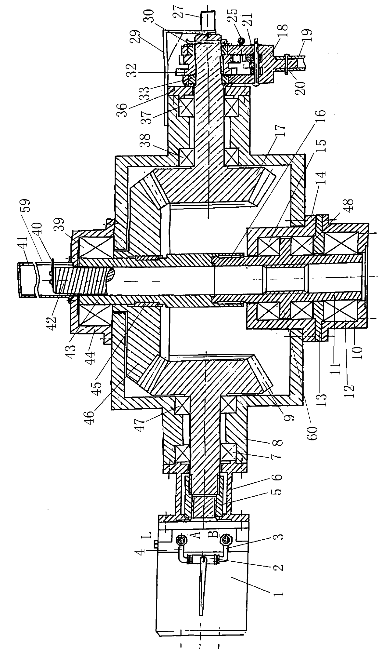

Image

  • Multi-rotary hydraulic valve
  • Multi-rotary hydraulic valve
  • Multi-rotary hydraulic valve

Examples


Embodiment 1

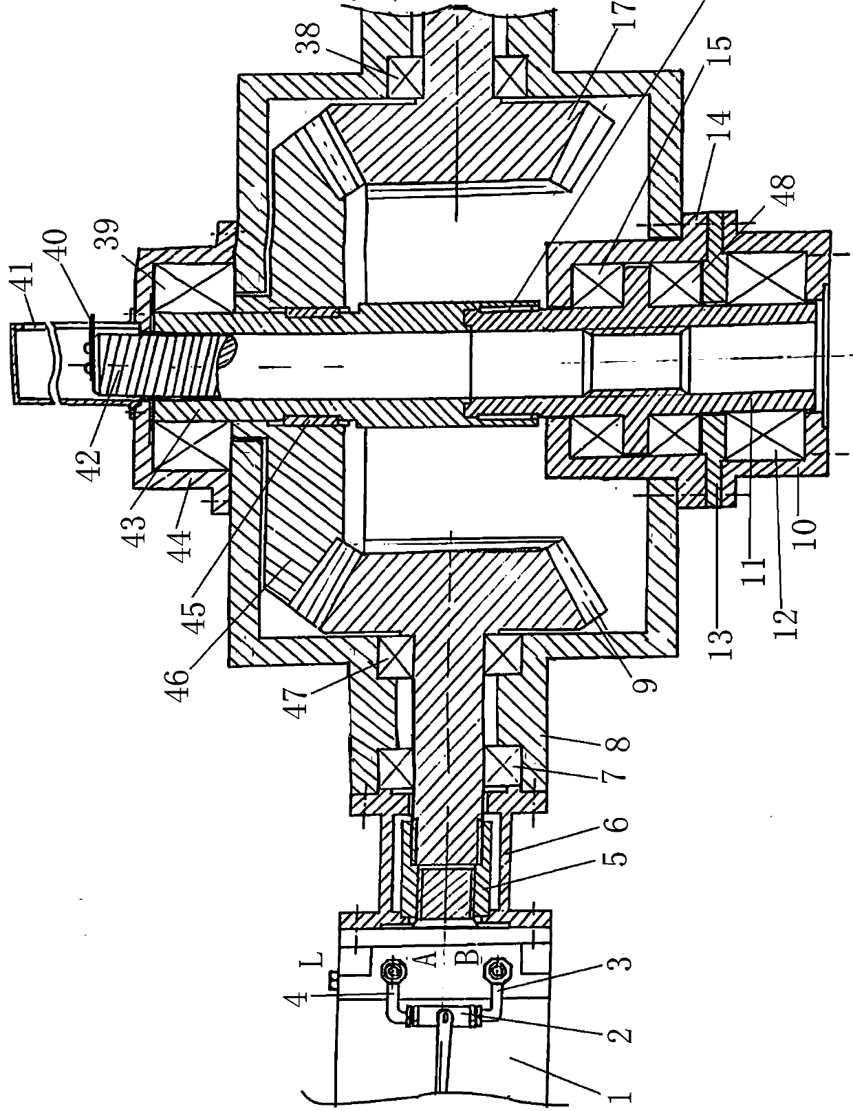
[0065] A multi-rotary hydraulic valve has a hydraulic motor 1 . The hydraulic motor 1 is a known standard series of products, which can be selected flexibly to ensure its matching, which can shorten the delivery cycle of hydraulic valves and reduce product prices, facilitate the standardization and serialization of this product, and overcome the hydraulic pressure of known multi-turn hydraulic valves. Direct motor drive is theoretically feasible and has outstanding advantages, but the design and manufacture are difficult, the construction period is long, the processing cost is high, and the degree of standardization is low, which is not conducive to the promotion and application of the superior technology of multi-turn hydraulic valves.

[0066] I have authorized three patents, the patent number is 201210158229.9 a multi-rotary hydraulic valve, 200610135071.8 rotary hydraulic valve, 200610135142.4 rotary hydraulic valve, the required hydraulic motor needs to be customized separ...

Embodiment 2

[0151] Embodiment 2 is basically the same as Embodiment 1, except that the bright stem valve is replaced by a dark stem valve, and the dark stem valve drives the valve stem (upper solid valve stem) 53 to rotate instead of moving up and down.

[0152] The lifting valve stem 42 , the valve driving bushing 43 and the lifting valve stem nut 11 in Embodiment 1 are replaced by a dark rod valve driving valve stem 53 .

[0153] The vertically arranged dark rod valve driving valve rod 53 upper end is fixedly connected with the large bevel gear 46 inner hole with the dark rod valve driving valve rod coupling key 76.

[0154] The lower end of the hidden rod valve driving valve stem 53 is provided with a lower rolling bearing for the valve stem, which is fixedly supported on the inner side of the gear box body 8 by the lower rolling bearing seat 54 of the valve stem.

[0155] Valve stem lower rolling bearing seat 54 bottom stretches out gear box body 8 edges and fixes.

[0156] The upper...


PUM


Abstract

The invention relates to a multi-rotary hydraulic valve which comprises a hydraulic motor, a decelerating booster, a valve transmission mechanism, an encoder, a valve and a connecting part. An outputtorque of the hydraulic motor is adjusted automatically according to change of a load in a valve opening and closing process to achieve an intelligent control mode and prevent vibration shock to the valve, so that the multi-rotary hydraulic valve is high in environmental adaptability, can be used in occasions where an electric valve is widely applied and working environments where the electric valve is not suitable, and can operate reliably. The multi-rotary hydraulic valve can be used in inflammable and explosive occasions, and humid, high pollution and high dust occasions. By adopting a method of a arranging a hydraulic system in another place, the risk of the multi-rotary hydraulic valve is avoided effectively, the opening of the valve can be controlled precisely, and a valve element can be self-locked effectively and reliably, too. The encoder improves the control precision of the hydraulic valve in the operating process, improves the automation control level, and can realize necessary conditions needed by a wireless monitoring function, so that the multi-rotary hydraulic valve is suitable for industrialization requirement in 5G age and has an emergency manual operating function.

Description

technical field [0001] The invention belongs to the field of valves, in particular to a multi-rotary hydraulic valve (multi-rotary hydraulic valve driven by a general hydraulic motor). Background technique [0002] As a key component in the pipeline transportation of water, oil and gas, valves are widely used in many fields such as petroleum, natural gas, oil and gas terminals, chemical industry, ships, power stations, metallurgy and municipal administration. In recent years, with the enlargement of engineering projects, the demand for large-diameter, that is, large-size valves has been increasing, and manual operation has become very difficult and cannot keep up with the requirements of the times. In order to meet the needs of the automation system, a variety of valve drive methods have appeared, such as electric valves driven by electric motors, pneumatic valves driven by cylinders, hydraulic valves driven by hydraulic cylinders, etc. In the application practice, it is fo...

Claims


Application Information

Patent Timeline
IPC IPC(8): F16K3/12F16K3/314F16K31/16F16K31/44F16K31/50F16K31/53F16K31/60F16K37/00
CPCF16K3/12F16K3/0254F16K3/314F16K31/16F16K31/44F16K31/50F16K31/53F16K31/60F16K37/0016
Inventor 徐学新
Owner 徐学新
Learn More