Piezocapacitance and piezoresistance coupled proximity sensing and contact force sensor

A sensor and contact force technology, which is applied in the measurement, instrument, and measurement force of the property force of piezoresistive materials. It can solve the problems of difficult to break through in response speed, complex measurement circuit, and parasitic capacitance, so as to increase contact perception. function, the effect of expanding the test range

Pending Publication Date: 2020-04-03
HARBIN INST OF TECH
View PDF8 Cites 9 Cited by
  • Summary
  • Abstract
  • Description
  • Claims
  • Application Information

AI Technical Summary

Problems solved by technology

The principle of the piezoelectric sensor is the piezoelectric effect. When the material is deformed by an external force in a certain direction, a polarization phenomenon will occur inside it, and positive and negative charges will appear on the two opposite surfaces, and it will recover when the external force is removed. To the uncharged state, the piezoelectric sensor has the advantages of high frequency response, high sensitivity, and large dynamic range, but the spatial resolution is low, the measurement circuit is complicated, and the stability is poor; the principle of the piezoresistive sensor is the piezoresistive effect. When subjected to stress, the stress causes changes in energy bands, energy shifts in energy valleys, and resistivity changes. Its advantages lie in high frequency response, high spatial resolution, and low noise interference, but poor repeatability, large power consumption, and large measurement range. Small; capacitive sensors use various types of capacitors as sensing elements, and convert the measured physical or mechanical quantities into capacitance changes. The conversion device mainly changes the relative area of ​​the electrodes, dielectric constant, etc., and has the advantages of high sensitivity and spatial resolution. High rate and large dynamic measurement range, but there is parasitic capacitance and is sensitive to noise; the principle of piezomagnetic sensor is the piezomagnetic effect. When the ferromagnetic material is subjected to external force, the internal stress will be generated, causing the permeability of the ferromagnetic material to decrease. The change can be converted into the magnitude of the force through the amplifying circuit. Its advantages are high sensitivity and small occupied volume, but the structure design is complex and the resolution is low.
[0004] During the use and transportation of the robot, it is inevitable that it will collide with other objects, especially in the process of high-speed movement, which will cause damage to the robot casing and even the internal structure, thereby greatly reducing the service life and greatly increasing the maintenance cost. User requirements for robot intelligence
Based on the above introduction and analysis of various tactile sensors, we found that sensors with a single measurement principle have defects in the measurement range, stability, sensitivity, resolution, etc., and cannot achieve wide-area coverage, and the response speed is difficult to break through milliseconds. The lack of contact perception function before collision, which limits the further development of tactile sensors

Method used


Image

  • Piezocapacitance and piezoresistance coupled proximity sensing and contact force sensor
  • Piezocapacitance and piezoresistance coupled proximity sensing and contact force sensor
  • Piezocapacitance and piezoresistance coupled proximity sensing and contact force sensor

Examples


Embodiment Construction

[0017] The technical solutions in the embodiments of the present invention will be clearly and completely described below in conjunction with the drawings in the embodiments of the present invention.

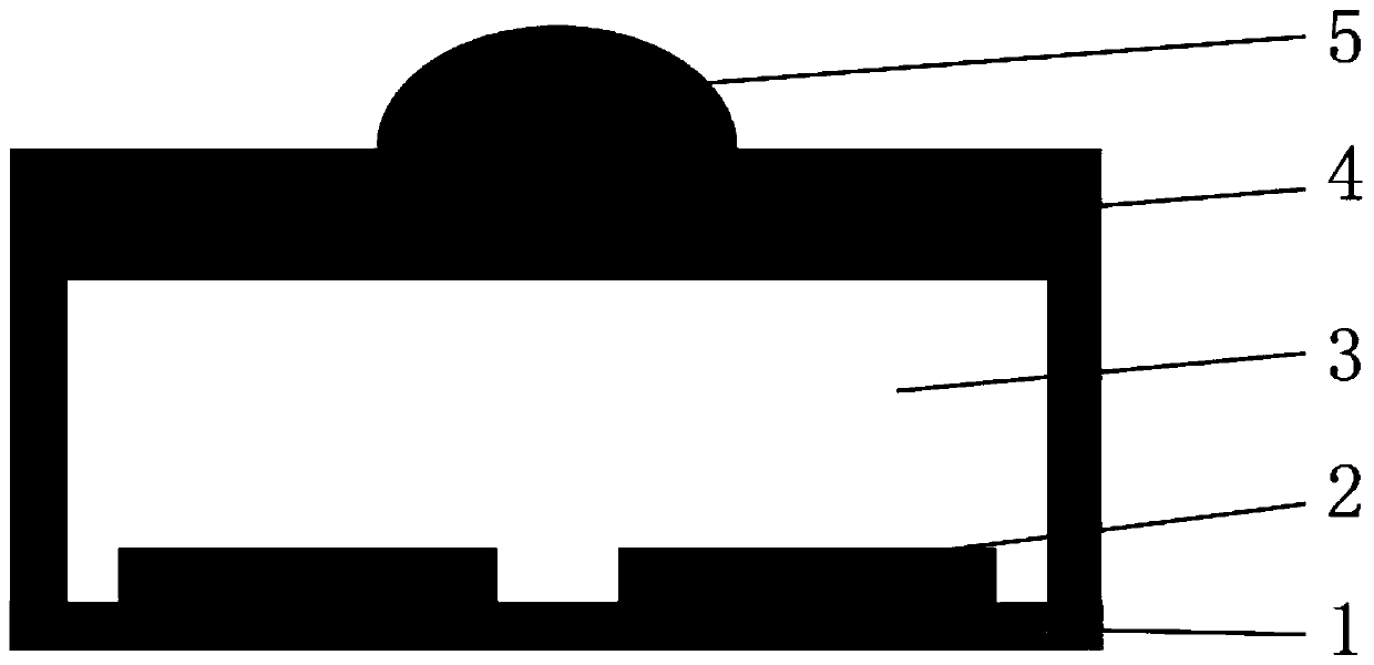
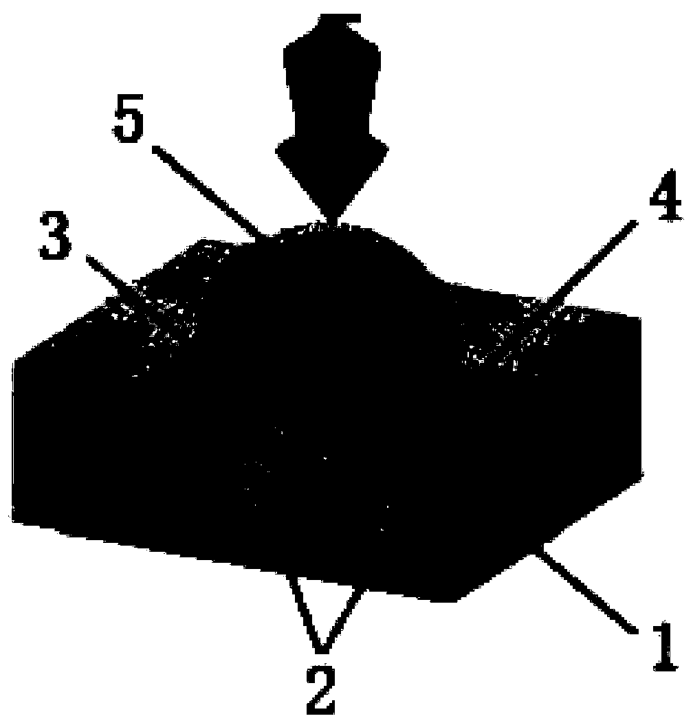
[0018] see Figure 1-4 Describe this embodiment, a proximity sensing and contact force sensor coupled with piezocapacitance and piezoresistive, which includes a flexible substrate 1, coplanar electrodes 2, piezoresistive elastic body 4 and surface protrusions 5, the flexible substrate 1 Located at the bottom, the coplanar electrode 2 is disposed on the flexible substrate 1, the piezoresistive elastomer 4 is a cavity structure, and the piezoresistive elastomer 4 is disposed above the flexible substrate 1 and the coplanar electrode 2, The piezoresistive elastomer 4 forms an air cavity 3 in the area enclosed by the flexible substrate 1, and the surface protrusion 5 is arranged on the upper surface of the piezoresistive elastomer 4. The piezoresistive elastomer 4 adopts low-dimensio...


PUM


Abstract

The invention provides a piezocapacitance and piezoresistance coupled proximity sensing and contact force sensor, belongs to the technical field of tactile safety, and particularly relates to a piezocapacitance and piezoresistance coupled proximity sensing and contact force sensor. The problems that a tactile sensor with a single detection principle is difficult to realize measurement of large-range force change, the response speed is difficult to break through the millisecond magnitude, and the contact sensing function before collision between an object and the sensor is lost are solved. Thepiezoresistive sensor comprises a flexible substrate, coplanar electrodes, piezoresistive elastomers and surface bulges, wherein the flexible substrate is located at the bottom, the coplanar electrodeis arranged on the flexible substrate, the piezoresistive elastomer is of a cavity structure, the piezoresistive elastomer is arranged above the flexible substrate and the coplanar electrode, an airhole is formed in an area defined by the piezoresistive elastomer and the flexible substrate, and the surface protrusion is arranged on the upper surface of the piezoresistive elastomer. The robot ismainly used for sensing external environment changes.

Description

technical field [0001] The invention belongs to the technical field of tactile safety, in particular to a pressure-capacitance and piezoresistive coupling proximity sensing and contact force sensor. Background technique [0002] With the continuous development and application of robot technology, the accurate, fast and predictable perception of external objects and environmental changes has become the focus of scholars' research, so the academic circles put forward the concept of intelligent robots, and the application of tactile sensors in intelligent robots Become the most important means for robots to perceive changes in the external environment. [0003] The current tactile sensors can be divided into piezoelectric, piezoresistive, capacitive, piezomagnetic, etc. according to the measurement principle. The principle of the piezoelectric sensor is the piezoelectric effect. When the material is deformed by an external force in a certain direction, a polarization phenomeno...

Claims


Application Information

Patent Timeline
Patent Type & Authority Applications(China)
IPC IPC(8): G01L1/14G01L1/18
CPCG01L1/142G01L1/18
Inventor 张甲葛传洋王振龙
Owner HARBIN INST OF TECH
Why Eureka
Try Eureka