
Fuel cell system and standby control method thereof

A fuel cell system and control method technology, applied in the direction of fuel cell control, fuel cells, fuel cell additives, etc., can solve the problems of not considering the durability and feasibility of air compressors, so as to shorten the experience time, avoid backflow, Effect of improving stability and service life

Active Publication Date: 2020-04-03
CHINA FIRST AUTOMOBILE
View PDF13 Cites 6 Cited by
  • Summary
  • Abstract
  • Description
  • Claims
  • Application Information

AI Technical Summary

Problems solved by technology

The system standby control of the working condition of the invention can switch between the static standby mode and the dynamic standby mode by comparing the accumulated energy consumed by the idling air compressor with the energy required to start the air compressor, but this patent still does not consider the frequent start and stop of the air compressor durable feasibility

Method used


Image

  • Fuel cell system and standby control method thereof
  • Fuel cell system and standby control method thereof
  • Fuel cell system and standby control method thereof

Examples


Embodiment

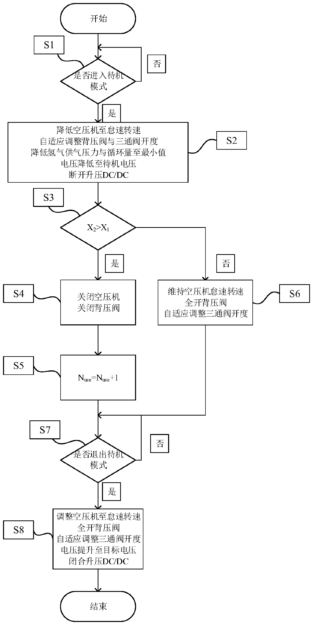
[0068] This embodiment provides a standby control method of a fuel cell system, which includes the following steps:

[0069] Step S1, it is judged whether the fuel cell system has received an instruction to enter the standby mode, if an instruction to enter the standby mode is received, step S2 is executed; if an instruction to enter the standby mode is not received, step S1 is executed;

[0070] Step S2: After the fuel cell system receives the instruction to enter the standby mode, it reduces the air compressor to its idle speed, adaptively adjusts the opening of the back pressure valve and the three-way valve, so that the air supply conditions for the cathode chamber of the fuel cell stack meet Fuel cell power consumption demand; adjust the hydrogen gas supply pressure and circulation volume to the minimum according to the air supply status; after the fuel cell stack voltage is pulled down to the idle voltage with a small current, disconnect the fuel cell stack and boost DC / DC Co...

Embodiment 1

[0109] (3) Compared with Example 1, the standby control method of the fuel cell system provided by Comparative Example 2 does not take into account the life factor of the air compressor. The standby mode of the fuel cell system is relatively single, and the use of the fuel cell system The service life has an adverse effect, which shows that embodiment 1 takes into account the start and stop service life of the air compressor, which is more conducive to the actual use of the car;

[0110] (4) Compared with Example 1, the standby control method of the fuel cell system provided by Comparative Example 3 maintains the open circuit voltage of the fuel cell at the voltage required for standby in the standby state, and the catalyst is not activated at this voltage, so The performance of the fuel cell stack is inferior to that of the first embodiment, which shows that the idling voltage adopted in the first embodiment is beneficial to improve the performance of the fuel cell stack.

[0111]...


PUM


Abstract

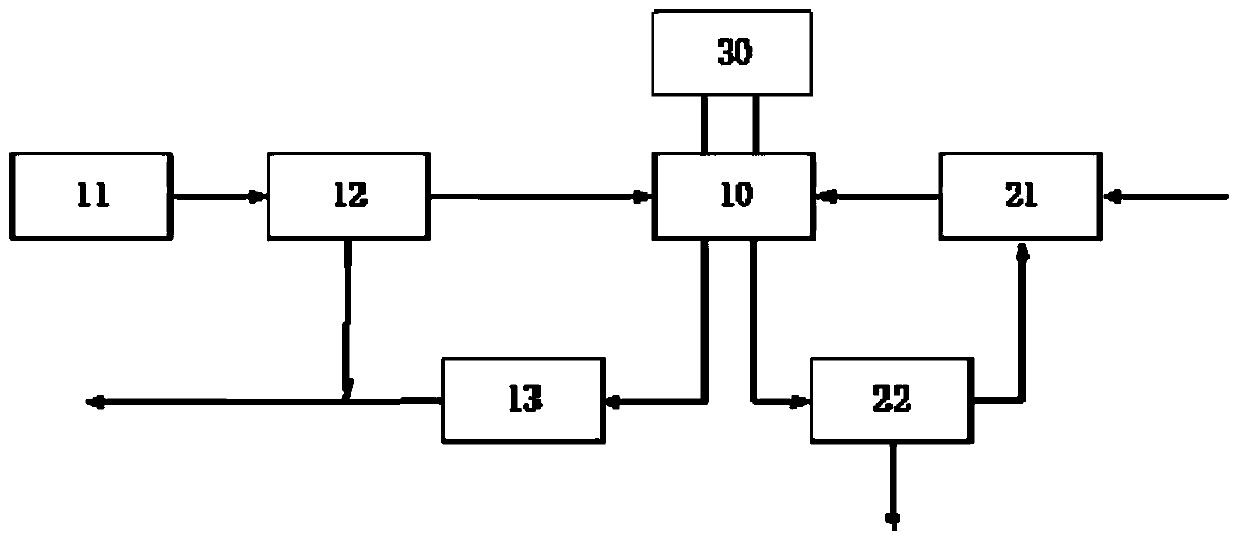
The invention relates to a fuel cell system and a standby control method thereof. The fuel cell system comprises a fuel cell stack, an air compressor, a shunt device, a back pressure valve, a hydrogensupply and return assembly, a water diversion and hydrogen discharge assembly and a boost DC / DC converter; the fuel cell stack comprises an anode chamber and a cathode chamber, the fuel cell stack isconnected with the boost DC / DC converter, an outlet of the air compressor is in fluid connection with an inlet of the cathode chamber and an outlet of the back pressure valve, and an inlet of the back pressure valve is connected with an outlet of the cathode chamber; the anode chamber inlet and the anode chamber outlet of the fuel cell stack are respectively connected with the hydrogen supply andreturn assembly and the water diversion and hydrogen discharge assembly, and a hydrogen discharge outlet of the water diversion and hydrogen discharge assembly is connected with an inlet of the hydrogen supply and return assembly. The standby control method solves the problems that the normal shutdown process is long in elapsed time and the service life of the fuel cell stack is influenced.

Description

Technical field [0001] The invention relates to the technical field of electric vehicles, in particular to a fuel cell system and a standby control method thereof. Background technique [0002] Fuel cell is a device that directly converts the chemical energy of fuel into electrical energy. It is known as the fourth-generation power generation technology after hydropower, thermal power, and nuclear power. It has the characteristics of high efficiency, low emissions, no pollution and diversified fuels. , Has a wide range of application prospects in the fields of automobiles, airplanes, submarines, communications, etc., especially in the automotive field. Fuel cell vehicles have the advantages of zero emissions, fast refueling, and long battery life, and are hailed as an important development direction for new energy vehicles in the future. [0003] The fuel cell outputs electric energy through the hydrogen-oxygen reaction, which is a series of electrochemical reaction, gas transfer, ...

Claims


Application Information

Patent Timeline
IPC IPC(8): H01M8/04082H01M8/04089H01M8/04746H01M8/04955H01M8/04992H01M8/2457H01M8/04223H01M8/043
CPCH01M8/04089H01M8/04097H01M8/04201H01M8/04223H01M8/04753H01M8/04955H01M8/04992H01M2250/20H01M8/043H01M8/2457Y02E60/50
Inventor 王宇鹏丁天威赵洪辉赵子亮都京浦及
Owner CHINA FIRST AUTOMOBILE
Learn More