Detection system and hydrogen detection method

A detection method and detection system technology, applied in measuring devices, instruments, and material analysis through optical means, can solve problems such as poor selectivity, low detection sensitivity, and slow signal response

Active Publication Date: 2020-04-07
THE HONG KONG POLYTECHNIC UNIV SHENZHEN RES INST
View PDF4 Cites 3 Cited by
  • Summary
  • Abstract
  • Description
  • Claims
  • Application Information

AI Technical Summary

Problems solved by technology

[0004] The main purpose of the present invention is to provide a detection system, aiming at solving techn

Method used


Image

  • Detection system and hydrogen detection method
  • Detection system and hydrogen detection method
  • Detection system and hydrogen detection method

Examples


preparation example Construction

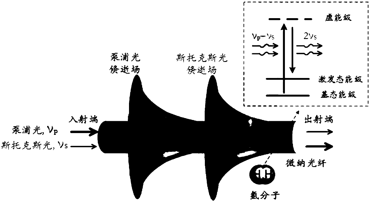
[0042] The embodiment of the present invention does not specifically limit the preparation of the micro-nano optical fiber, which can be obtained by direct drawing from a common single-mode optical fiber, or directly purchased from the market.

[0043] Preferably, the diameter of the micro-nano fiber is 0.3-0.9 times the wavelength of the pump light.

[0044] When the diameter of the micro-nano fiber is 0.9 times larger than the wavelength of the pump light, the proportion of the evanescent field decreases, the efficiency of stimulated Raman scattering decreases, and the sensitivity decreases; when the diameter of the micro-nano fiber is smaller than 0.3 times the wavelength of the pump light, the evanescent field The intensity decreases, the stimulated Raman scattering efficiency decreases, and the sensitivity decreases.

[0045] Preferably, the length of the micro-nano optical fiber is 1-100 mm.

[0046] Theoretically, the longer the micro-nano fiber, the higher the sensiti...

Embodiment 1

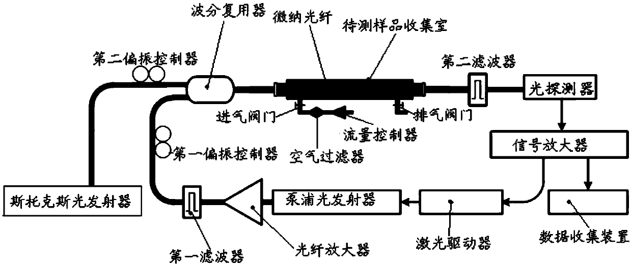
[0075] This embodiment provides a method for detecting hydrogen gas, which is implemented based on the above-mentioned figure 2 The specific operation steps of the detection system shown are as follows:

[0076] 1. Keep the intake valve and exhaust valve open, and the gas to be tested enters the sample collection chamber to be tested through the flow controller and the air filter in turn;

[0077] Among them, the diameter of the micro-nano optical fiber arranged in the sample collection chamber to be tested is 0.7 μm, and the length is 48 mm; the diameter of the waist region of the micro-nano optical fiber is 700 nm, and the length of the waist region is 48 mm.

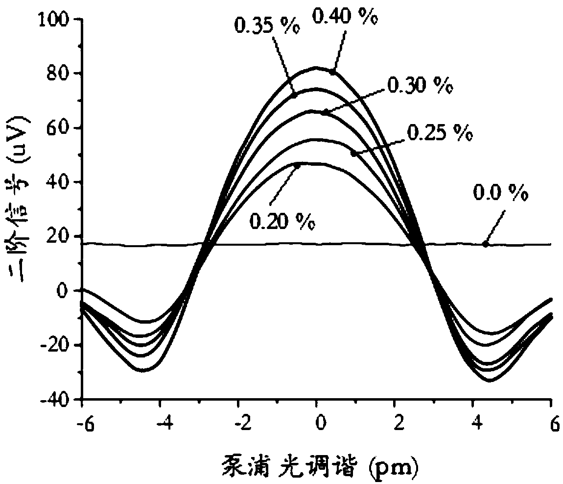
[0078] 2. The pump light and Stokes light are injected from the input end of the micro-nano fiber through the laser driving device of the control module, and the frequency of the pump light injected into the micro-nano fiber is adjusted by the laser driving device of the control module to be 195.6THz, power 300mW, S...


PUM

PropertyMeasurementUnit
Lengthaaaaaaaaaa
Diameteraaaaaaaaaa
Lengthaaaaaaaaaa

Abstract

The invention belongs to the technical field of gas trace detection, and particularly relates to a hydrogen detection method and system. The hydrogen detection method is based on a micro-nano opticalfiber. The micro-nano optical fiber comprises an input end and an output end. The method comprises the following steps: taking pump light and Stokes light as incident light sources; emitting pump light and Stokes light from the input end of a micro-nano optical fiber, evanescent fields generated by the pump light and the Stokes light coinciding with each other, the coincident evanescent fields interacting with hydrogen in a to-be-detected sample to generate a stimulated Raman scattering process taking rotational Raman transition of hydrogen molecules as a medium, and converting part of the pump light into the Stokes light; detecting a gain signal of the Stokes light output from the output end of the micro-nano optical fiber, and converting according to the relationship between the gain ofthe Stokes light and the hydrogen concentration to obtain the concentration of the hydrogen in the to-be-detected sample; wherein the frequency difference between the pump light and the Stokes light is equal to the rotational Raman transition frequency of hydrogen. The detection sensitivity is high and the signal response is fast.

Description

technical field [0001] The invention belongs to the technical field of gas trace detection, and in particular relates to a detection system and a hydrogen detection method. Background technique [0002] Hydrogen is an important chemical raw material and an important clean energy source, which has been widely used in a series of industrial fields. Hydrogen molecules are very small, and are prone to leakage during storage and transportation. When the hydrogen content in the air reaches more than 4%, a strong explosion is likely to occur, so trace hydrogen detection is very important. [0003] At present, the optical fiber-based trace hydrogen detection method mainly uses optical fibers coated with specific metals (such as palladium and platinum, etc.) on the surface. The metal coated on the surface of the optical fiber will undergo physical or chemical changes when exposed to hydrogen, and then the absorption of the probe light Either the reflectivity changes, or the optical ...

Claims


Application Information

Patent Timeline
IPC IPC(8): G01N21/65
CPCG01N21/658
Inventor 靳伟齐云赵焱鲍海泓何海律
Owner THE HONG KONG POLYTECHNIC UNIV SHENZHEN RES INST
Why Eureka
Try Eureka