
Heat pump driven direct expansion type temperature and humidity separately-controlled heat recovery type solution humidity adjusting fresh air unit

A fresh air unit and heat recovery technology, applied in heat recovery systems, heating methods, space heating and ventilation, etc., can solve the problems of low heat transfer efficiency of heat exchangers, high cost, low efficiency of heat pump systems, etc. Effects of wind quality, efficiency improvement, and cost reduction

Inactive Publication Date: 2020-04-10
孙广军
View PDF0 Cites 2 Cited by
  • Summary
  • Abstract
  • Description
  • Claims
  • Application Information

AI Technical Summary

Problems solved by technology

[0006] The main purpose of the present invention is to provide a heat pump-driven direct expansion type temperature-humidity control heat recovery type solution humidity control fresh air unit; to solve the problem of low heat exchange efficiency of the heat exchanger in the prior art and poor return air heat recovery effect, The solution dehumidification fresh air unit cannot meet the requirements of energy saving and anti-corrosion at the same time, and the efficiency of the heat pump system is low.

Method used


Image

  • Heat pump driven direct expansion type temperature and humidity separately-controlled heat recovery type solution humidity adjusting fresh air unit
  • Heat pump driven direct expansion type temperature and humidity separately-controlled heat recovery type solution humidity adjusting fresh air unit
  • Heat pump driven direct expansion type temperature and humidity separately-controlled heat recovery type solution humidity adjusting fresh air unit

Examples


Embodiment Construction

[0022] The technical solutions in the embodiments of the present invention will be clearly and completely described below in conjunction with the accompanying drawings in the embodiments of the present invention. Obviously, the described embodiments are only a part of the embodiments of the present invention, rather than all the embodiments. Based on the embodiments of the present invention, all other embodiments obtained by those of ordinary skill in the art without creative work shall fall within the protection scope of the present invention.

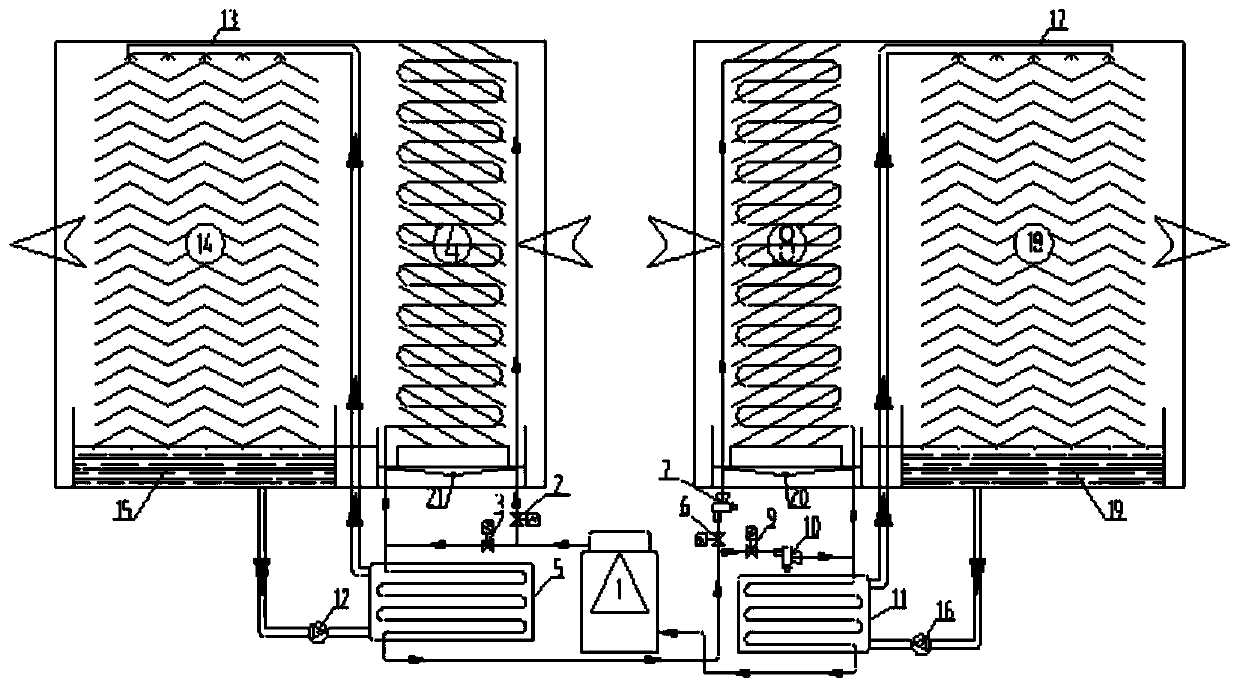
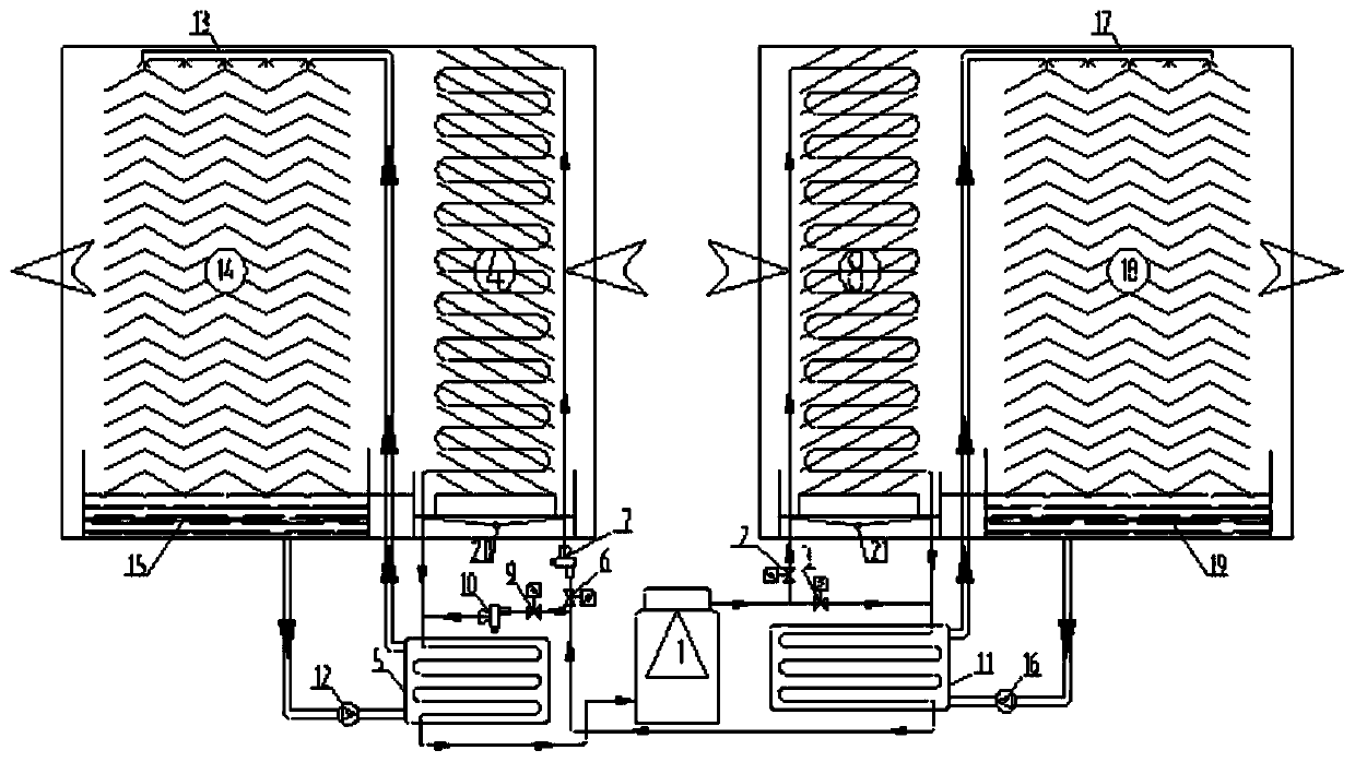
[0023] Such as figure 1 As shown, the example of the present invention includes compressor 1, solenoid valve one 2, solenoid valve two 3, condensation heat recovery coil 4, condenser 5, solenoid valve three 6, expansion valve one 7, direct expansion pre-cooling and preheating coil 8. Solenoid valve four 9, expansion valve two 10, and evaporator 11 are connected by pipelines to form a heat pump system. Three-way pipes are set at the outlet...


PUM


Abstract

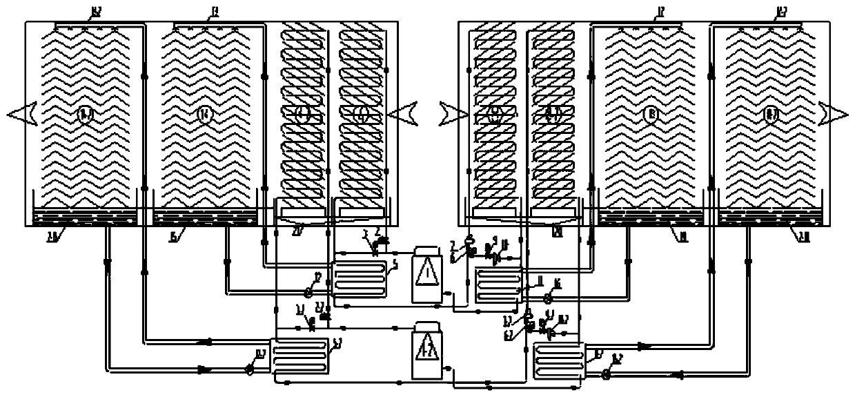
The invention relates to a direct expansion type temperature and humidity separately-controlled heat recovery type solution humidity adjusting fresh air unit. The fresh air unit comprises a heat pumpsystem, a solution regeneration system and a solution humidity adjusting system, wherein the heat pump system is formed through pipeline connection of a compressor, a heat recovery coil pipe, a condenser, an expansion valve, a pre-cooling and preheating coil pipe and an evaporator; the solution regeneration is formed through pipeline connection of a regeneration solution pump, a condenser, a regeneration solution spraying pipe, regeneration solution wet film filler and a regeneration solution collecting tank; the solution humidity adjusting system is formed through pipeline connection of a humidity adjusting solution pump, an evaporator, a humidity adjusting solution spraying pipe, humidity adjusting solution wet film filler and a humidity adjusting solution collecting tank; the heat recovery coil pipe and the regeneration solution wet film filler form a heat recovery return air solution regeneration channel; and a fresh air humidity adjusting air supply channel is formed by the pre-cooling and pre-heating coil pipe and the humidity adjusting solution wet film filler. The direct expansion type temperature and humidity separately-controlled heat recovery type solution humidity adjusting fresh air unit can be widely applied to places needing to provide dry fresh air.

Description

Technical field [0001] The invention relates to a fresh air unit, in particular to a heat pump-driven direct expansion type temperature and humidity sub-control heat recovery type solution humidity adjustment fresh air unit. Background technique [0002] Most of the existing air-conditioning systems adopt condensation and dehumidification treatment methods, using refrigerators to prepare low-temperature chilled water, reducing the air temperature to below the dew point, so as to achieve the dehumidification process of the fresh air. In order to meet the dehumidification requirements, the chilled water temperature is much lower than the cooling point. The required cold water temperature causes the evaporation temperature of the refrigerator to decrease, thereby reducing the coefficient of performance of the refrigerator. At present, the solution dehumidification equipment uses salt solution with moisture absorption and dehumidification characteristics as the working medium, and th...

Claims


Application Information

Patent Timeline
Patent Type & Authority Applications(China)
IPC IPC(8): F24F3/14F24F3/16F24F11/65F24F11/74F24F12/00F24F13/30F24F110/10F24F110/20
CPCF24F3/1405F24F12/006F24F13/30F24F11/65F24F11/74F24F2110/10F24F2110/20F24F8/10F24F8/117Y02B30/56Y02B30/70
Inventor 孙广军
Owner 孙广军
Learn More