A Closed Cycle Drying System Based on Two-Stage Solution Dehumidification

A solution dehumidification and closed-circuit circulation technology, which is applied in the direction of drying solid materials, drying gas arrangement, heating to dry solid materials, etc., can solve the problem of limited dehumidification capacity, achieve high dehumidification efficiency, reduce system energy consumption, and low energy consumption Effect

Active Publication Date: 2021-07-30
ZHEJIANG UNIV OF TECH +1
View PDF6 Cites 2 Cited by
  • Summary
  • Abstract
  • Description
  • Claims
  • Application Information

AI Technical Summary

Problems solved by technology

Chinese patent CN109539703A discloses a drying device using high-temperature solution dehumidification technology, which has a better energy-saving effect, but the solution in the solution dehumidification system dehumidifies the drying medium under high-temperature conditions, and it will no longer be used in occasions with high dehumidification requirements. Applicable, and the device uses a first-stage dehumidification system with limited dehumidification capacity

Method used


Image

  • A Closed Cycle Drying System Based on Two-Stage Solution Dehumidification
  • A Closed Cycle Drying System Based on Two-Stage Solution Dehumidification

Examples


Embodiment 1

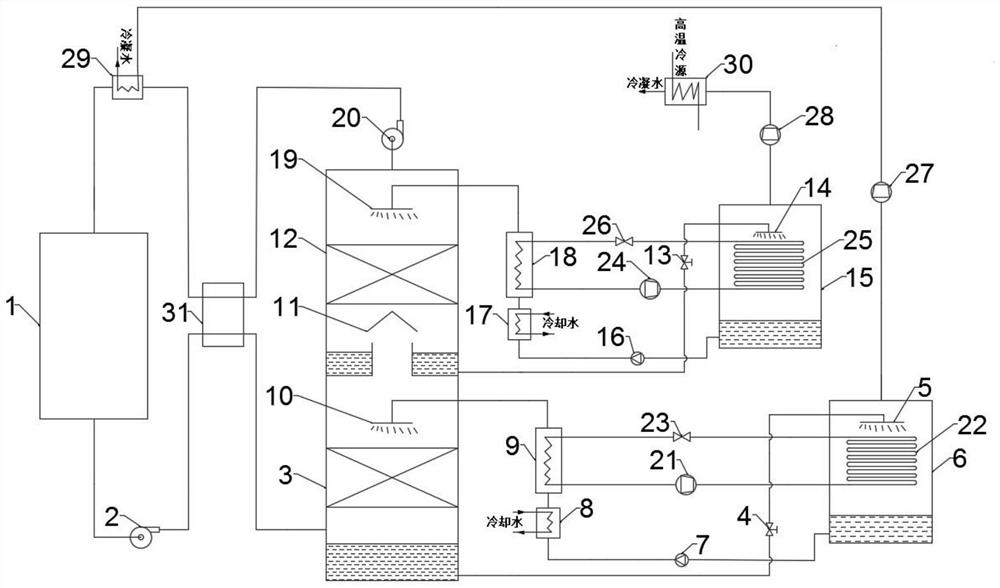
[0042] The schematic diagram of the device structure of the closed-loop drying system based on two-stage solution dehumidification in this embodiment is as follows: figure 1 shown. control figure 1 , both the high-pressure steam condenser 29 and the low-pressure steam condenser 30 can adopt a heat exchanger structure.

[0043] After the hygroscopic saline solution in the primary vacuum regeneration tank 6 boils, the moisture in the hygroscopic saline solution becomes water vapor, which is pressurized by the compressor III 27 and enters the high-pressure steam condenser 29 to condense into liquid water, which is condensed and released The heat is used to heat the drying medium air (that is, the low-temperature and low-humidity drying medium drawn by the second fan 20 is preheated through the cold fluid passage of the heat exchange device 31, and then further heated through the cold fluid passage of the high-pressure steam condenser 29 to form High-temperature and high-humidit...

Embodiment 2

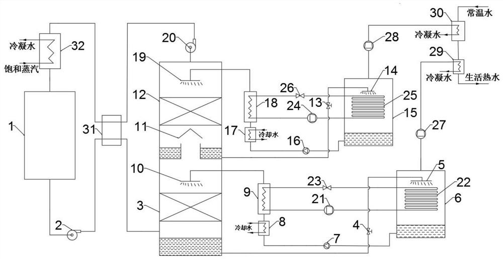
[0047] The schematic diagram of the device structure of the closed-loop drying system based on two-stage solution dehumidification in this embodiment is as follows: figure 2 shown. control figure 2 , both the high-pressure steam condenser 29 and the low-pressure steam condenser 30 can adopt a heat exchanger structure.

[0048] control figure 2 , the top of the first-stage vacuum regeneration tank 6 is connected by a pipeline through the hot fluid channel of the compressor III 27 and the high-pressure steam condenser 29, and the compressor IV 28 and the low-pressure steam condenser 30 of the second-stage vacuum regeneration tank 15 top pass through The hot fluid passages are connected by pipelines, and normal temperature water flows through the cold fluid passages of the low-pressure steam condenser 30 and the cold fluid passages of the high-pressure steam condenser 29 in sequence, and is heated to form domestic hot water. Both the heat of condensation in the high-pressur...


PUM


Abstract

The invention discloses a closed-circuit circulation drying system based on two-stage solution dehumidification, including a drying medium circulation subsystem, a first-stage solution dehumidification-regeneration circulation subsystem, a second-stage solution dehumidification-regeneration circulation subsystem, and a first heat pump cycle subsystem and the second heat pump cycle subsystem. The invention adopts two-stage solution dehumidification technology to dehumidify the drying medium, which solves the problems of easy freezing of the heat exchanger and high energy consumption in the traditional cooling and dehumidification process; the vacuum technology is used to regenerate the hygroscopic solution, which reduces the energy consumption of solution regeneration At the same time, the compression technology is used to recycle the generated secondary steam, which solves the problem that the latent heat of water vapor is not used in the traditional cooling and dehumidification process; the mechanical heat pump technology is used to adjust the temperature of solution dehumidification and regeneration, and the energy utilization rate of the system is improved.

Description

technical field [0001] The invention relates to the technical field of drying, in particular to the field of closed cycle drying based on two-stage solution dehumidification. Background technique [0002] The traditional closed-circuit drying system is to cool the high-temperature and high-humidity drying medium after dust removal to below the dew point temperature, remove the moisture in the drying medium by cooling, and then heat the cooled and dehumidified drying medium to the air supply temperature and send it to the drying machine again. In the device, the energy consumption in the whole process is relatively large; a large amount of latent heat of water vapor in the drying medium has not been recycled; the cooling device used to cool the high-temperature and high-humidity drying medium below the dew point temperature is prone to freezing, breeding bacteria, and seriously affecting Product quality and dehumidification effect. [0003] The solution dehumidification tech...

Claims


Application Information

Patent Timeline
Patent Type & Authority Patents(China)
IPC IPC(8): F26B3/08F26B21/00F26B21/08F26B25/00
CPCF26B3/08F26B21/001F26B21/086F26B25/005
Inventor 程榕张衡郑燕萍杨阿三李琰君贾继宁屠美玲
Owner ZHEJIANG UNIV OF TECH
Why Eureka
Try Eureka