Method and system for determining position of strain gauge of dynamometric wheel set
A technology for measuring wheelset and determining method, which is applied in the direction of measuring device, force/torque/work measuring instrument, force/torque/work measuring instrument calibration/test, etc. higher question
- Summary
- Abstract
- Description
- Claims
- Application Information
AI Technical Summary
Problems solved by technology
Method used
Image

Examples
Embodiment 1
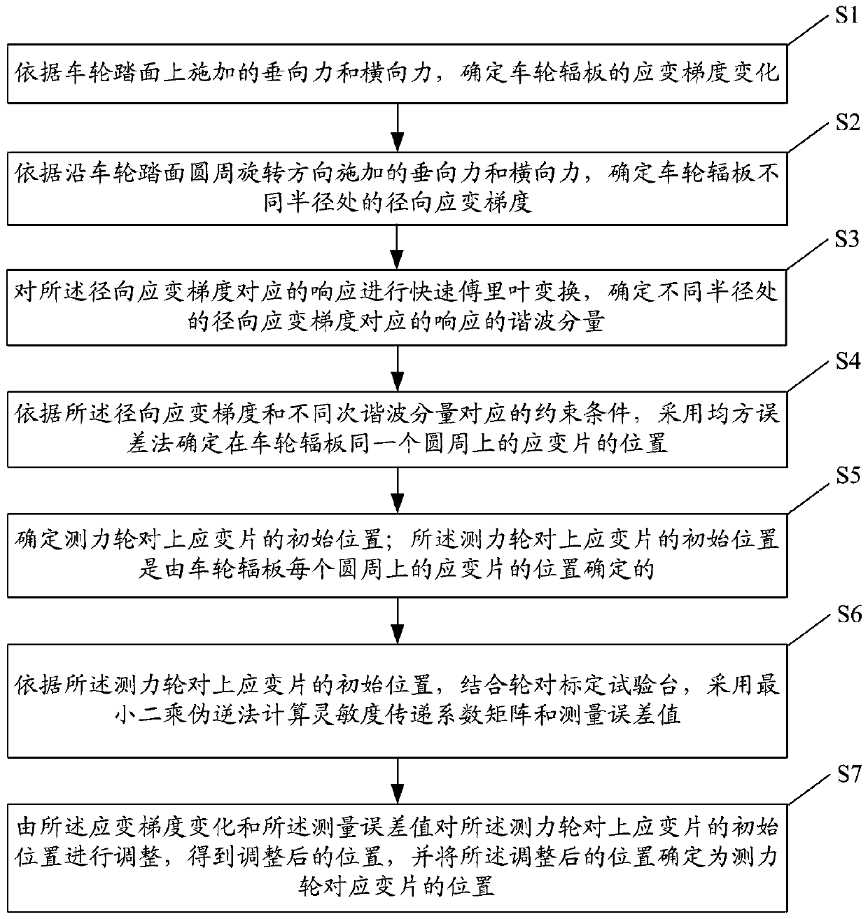
[0077] figure 1 It is a flow chart of a method for determining the position of a force measuring wheel pair of strain gauges in Embodiment 1 of the present invention. see figure 1 , the method for determining the position of the force measuring wheel pair of strain gauges in this embodiment includes:
[0078] Step S1: Determine the strain gradient change of the wheel web according to the vertical force and lateral force applied on the wheel tread.
[0079] Step S2: Determine the radial strain gradient at different radii of the wheel web plate according to the vertical force and lateral force applied along the rotation direction of the wheel tread circumference.
[0080] The step S2 specifically includes:
[0081] According to the radial strain gradient and even-order harmonic constraint conditions, the first included angle is determined by using the mean square error method; the first included angle is the included angle between the first strain gauge and the second strain ...
Embodiment 2
[0109] Aiming at the problems of low test accuracy, insufficient operation reliability, oversimplified calibration method, no consideration of the influence of wheel wear, and difficulty in long-term follow-up testing of existing force-measuring wheel sets, an optimal strain measurement method for force-measuring wheelsets was proposed. Chip layout optimization and least square error control calibration, by strengthening the optimal layout control of the measurement connection system, by using neural network technology to analyze and diagnose the test system, in order to improve the test accuracy of the force measuring wheel set, with high A dynamometric wheel set method for operational reliability and self-diagnostic test system failure function.
[0110] The train of thought of the method for determining the position of the force measuring wheel pair strain gauges provided in this embodiment is as follows:
[0111] In order to determine the optimal arrangement of the strain ...
Embodiment 3
[0200] Such as Figure 5 As shown, the force measuring wheel pair strain gauge position determination system provided in this embodiment includes:
[0201] The gradient change determination module 501 is configured to determine the strain gradient change of the wheel web according to the vertical force and lateral force applied on the wheel tread.
[0202] The radial strain value calculation module 502 is used to determine the radial strain gradient at different radii of the wheel web according to the vertical force and lateral force applied along the wheel tread circumferential rotation direction.
[0203] The harmonic component calculation module 503 is configured to perform fast Fourier transform on the response corresponding to the radial strain gradient, and determine the harmonic component of the response corresponding to the radial strain gradient at different radii.
[0204] The strain gauge position determination module 504 is configured to determine the position of ...
PUM
 Abstract
Description
Claims
Application Information