Bidirectional extrusion oily sludge treatment device

A two-way extrusion and sludge treatment technology, which is applied in sludge treatment, water/sludge/sewage treatment, liquid separation, etc., can solve the problems of sludge accumulation, increased thickness of oil-water transition layer, and reduced efficiency, etc., to achieve Avoid the accumulation of material at the tail, improve efficiency and increase the effect of extrusion force

Inactive Publication Date: 2020-04-14
谢晓永
View PDF1 Cites 3 Cited by
  • Summary
  • Abstract
  • Description
  • Claims
  • Application Information

AI Technical Summary

Problems solved by technology

[0002] At present, the waste oil produced in the crude oil production process generally only undergoes simple heating and gravity sedimentation treatment in the waste oil recovery process to improve its fluidity and reduce pollution according to the level of mechanical impurities, viscosity and temperature in the waste oil. The silt in pipelines and processing equipment caused by mud and sand in the oil, and even without any pretreatment, the dirty oil is directly mixed back into the fresh production fluid. The stability of the oil-water emulsion in oil, the dirty oil mixed into the freshly produced fluid often leads to the increase of the oil content in the water released by the free water remover, the increase of the dehydration current of the electric dehydrator or even the collapse of the electric field, and the oil-water transition layer in the dehydration tank Thickness increases, and in severe cases, the moisture content of crude oil out of the ore will exceed the standard
[0003] Chinese Patent Announcement No. CN209519467U proposes a treatment device for oily sludge in oil fields, which can effectively mix oil evenly, effectively remove sludge in oil, and facilitate oil purification, but it is different from existing equipment The same thing is that when the sludge is squeezed, one-way extrusion is adopted, and it is easy to accumulate sludge at the extrusion position. If things go on like this, it will affect the normal use of the equipment and reduce the efficiency

Method used


Image

  • Bidirectional extrusion oily sludge treatment device
  • Bidirectional extrusion oily sludge treatment device
  • Bidirectional extrusion oily sludge treatment device

Examples


Embodiment 1

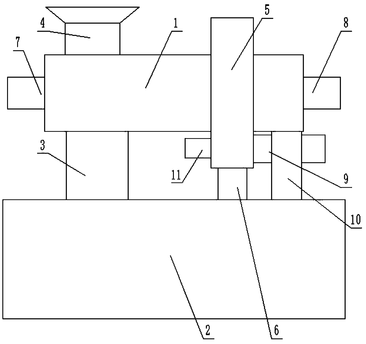
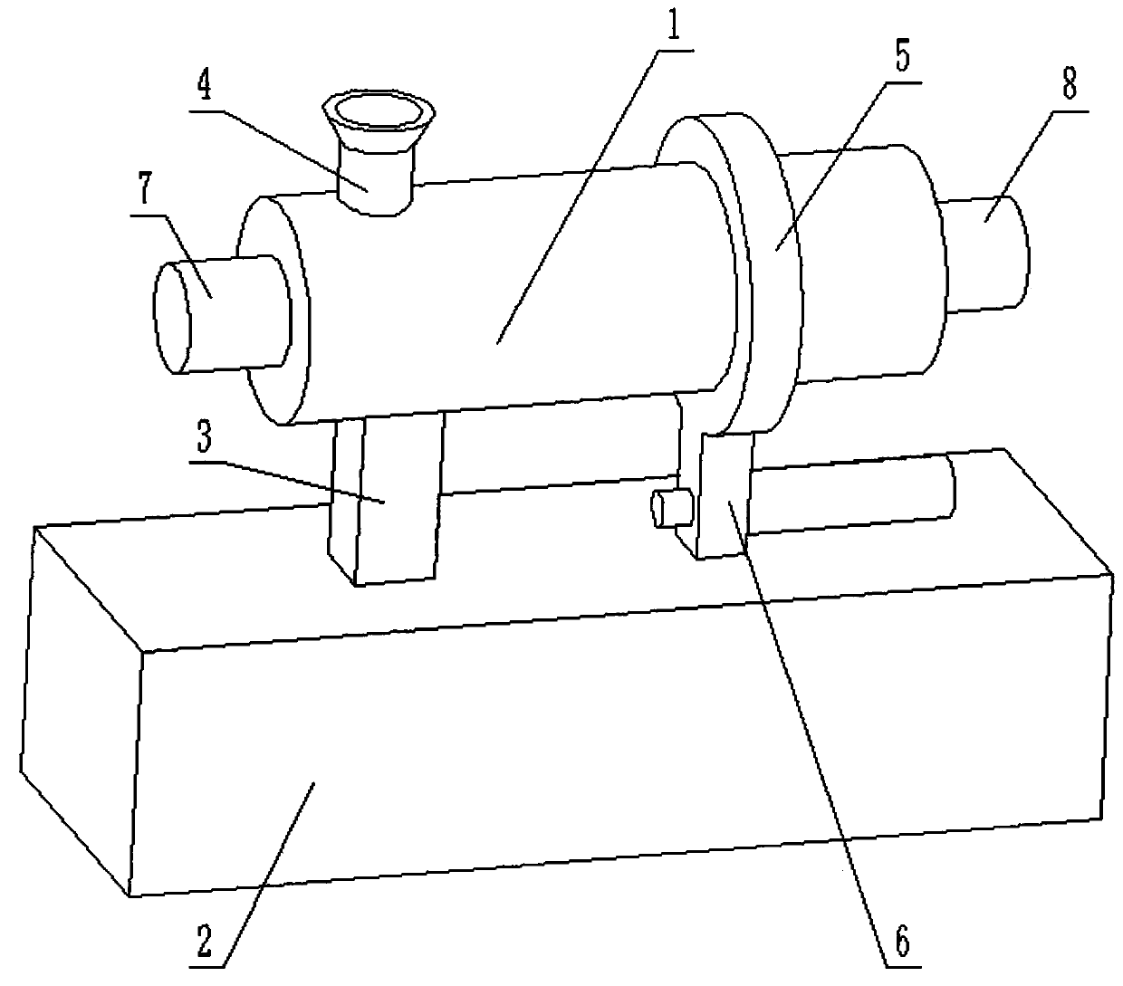
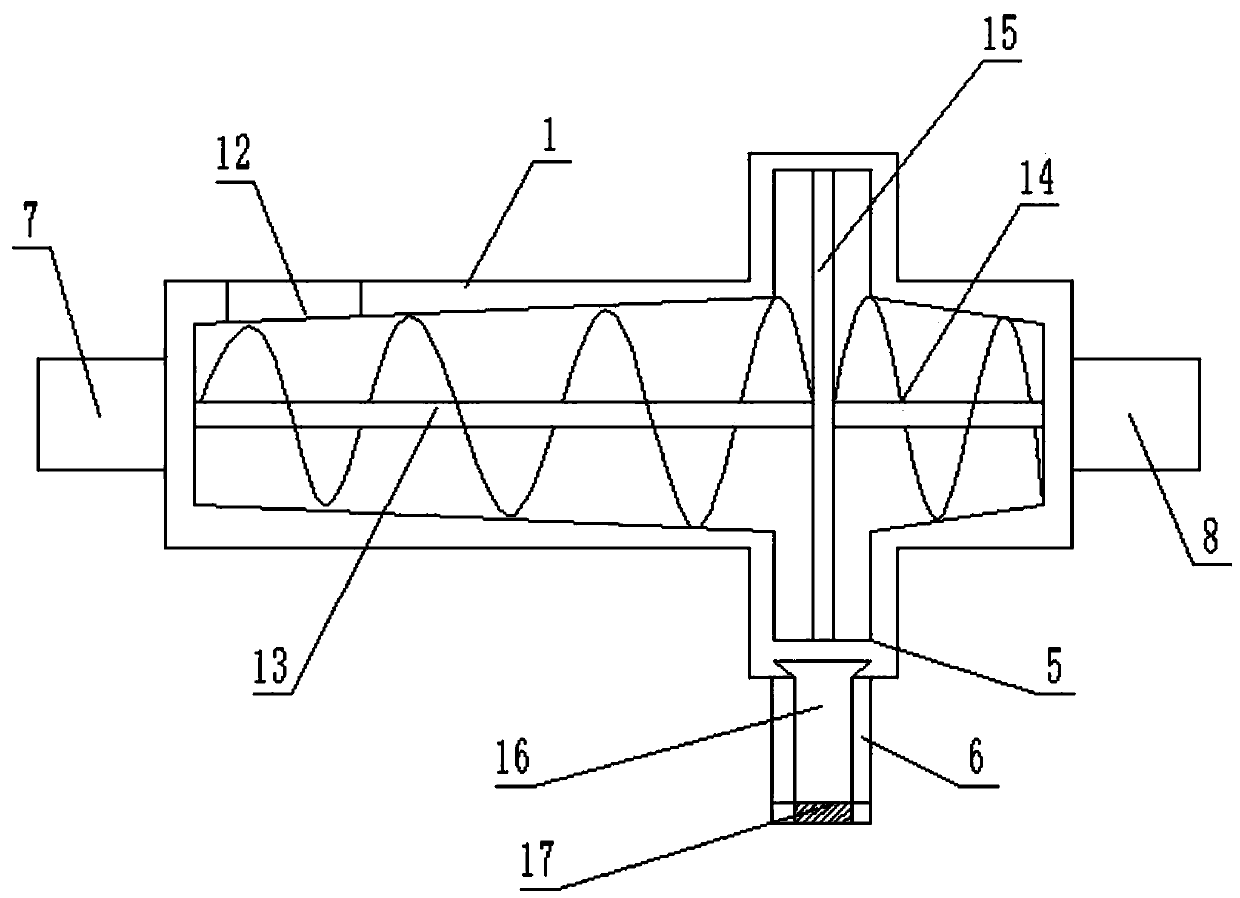
[0022] see Figure 1-3 , a two-way extrusion oily sludge treatment device, including a two-way extrusion cylinder 1 and a static layered box 2, the two-way extrusion cylinder 1 is fixed above the static layered box 2 and communicated with the static layered box 2 , between the two-way extrusion cylinder 1 and the static stratification box 2, a main support frame 3 and a secondary support frame 10 for supporting and fixing the two-way extrusion cylinder 1 are provided, and a feeding material is provided on the top of the two-way extrusion cylinder 1. The hopper 4 and the feed hopper 4 are used to transport the oily sludge into the two-way extrusion cylinder 1, and the two-way extrusion cylinder 1 is provided with an extrusion ring 5, and the inside of the extrusion ring 5 is connected with the inside of the two-way extrusion cylinder 1 In general, a vertical rod 15 is arranged in the extrusion ring 5, and a positive rotation auger 13 and a reverse rotation auger 14 are respecti...

Embodiment 2

[0028] refer to Figure 4 , on the basis of Embodiment 1, the mud outlet pipe 9 includes a cylindrical pipe body, which is arranged in a horizontal direction, and an output auger 18 coaxially arranged with it is provided in the cylindrical pipe body, and at the front end of the cylindrical pipe body An output motor 11 is provided, the output end of the output motor 11 is connected with the output auger 18, when the sludge is output, the drive motor is started to drive the output auger 18 to rotate, and the output auger 18 will filter the channel 16 The sludge inside is delivered to the tail of the mud outlet pipe 9, and when the sludge is output, the first drive motor 7 and the second drive motor 8 are started at the same time, so that the sludge in the two-way extrusion cylinder 1 is completely output.

[0029] Further, the tail end of the mud outlet pipe 9 is provided with a cover 19, and the cover 19 is threadedly connected with the cylindrical pipe body. When extruding, th...

Embodiment 3

[0031] refer to Figure 5, on the basis of Embodiment 1, a vertical partition 20 is provided in the static layered box 2, and the two sides of the partition 20 are respectively a static chamber 22 and a transfer chamber 23, and the screening channel 16 and The static chamber 22 is connected, and a communication port 21 is provided on the top of the partition plate 20. The communication port 21 is used to transfer the oil in the static chamber 22 to the transfer chamber 23, and a water supplement is inserted on the side wall of the static chamber 22. Pipe 24, water replenishing pipe 24 is used for adding water to the static cavity 22, when carrying out static stratification, because the density is different, the oil will float above the water, transfer in the transfer cavity 23 through the communication port 21, and when the liquid volume When it is less, water can be added to the static cavity 22 through the water supply pipe 24, thereby improving the liquid level position in ...


PUM


Abstract

The invention discloses a bidirectional extrusion oily sludge treatment device. The device comprises a two-way extrusion cylinder and a standing layering box, the two-way extrusion cylinder is fixed above the standing layering box and communicates with the standing layering box, a main supporting frame and an auxiliary supporting frame which are used for supporting and fixing the two-way extrusioncylinder are arranged between the two-way extrusion cylinder and the standing layering box, and a feeding hopper is arranged at the top of the two-way extrusion cylinder. When the device is used forcarrying out treatment work; oily sludge is conveyed into the two-way extrusion cylinder through the feeding hopper. A first drive motor is started, a forward-rotation packing auger is used for conveying sludge to an extrusion ring and extruding the sludge; liquid components and solid components in the sludge are separated; under the extrusion effect, the sludge is transferred into the standing layering box through a screening channel, meanwhile, a second driving motor is started, the sludge is extruded from the other side of the two-way extrusion cylinder through a reverse selection packing auger, the problem of material accumulation at the tail of the extrusion cylinder easily caused by one-way extrusion is solved, and the liquid precipitation efficiency is improved.

Description

technical field [0001] The invention relates to petrochemical equipment, in particular to a two-way extrusion oily sludge treatment device. Background technique [0002] At present, the waste oil produced in the crude oil production process generally only undergoes simple heating and gravity sedimentation treatment in the waste oil recovery process to improve its fluidity and reduce pollution according to the level of mechanical impurities, viscosity and temperature in the waste oil. The silt in pipelines and processing equipment caused by mud and sand in the oil, and even without any pretreatment, the dirty oil is directly mixed back into the fresh production fluid. The stability of the oil-water emulsion in oil, the dirty oil mixed into the freshly produced fluid often leads to the increase of the oil content in the water released by the free water remover, the increase of the dehydration current of the electric dehydrator or even the collapse of the electric field, and th...

Claims


Application Information

Patent Timeline
Patent Type & Authority Applications(China)
IPC IPC(8): C02F11/121B01D17/032
CPCB01D17/0214C02F11/121
Inventor 谢晓永
Owner 谢晓永
Why Eureka
Try Eureka