
Fluid conveying pipeline, preparation method thereof and leakage detection system

A technology for fluid transmission and pipeline leakage, applied in pipeline systems, pipeline protection, pipeline anti-corrosion/rust protection, etc., can solve problems such as inability to cover long distances, easy corrosion of pipelines, poor detection accuracy, etc., and reduce the time for laying costs , high precision, not easy to corrode

Inactive Publication Date: 2020-04-14
WUHAN MARINE ELECTRIC PROPULSION RES INST CHINA SHIPBUILDING IND CORP NO 712 INST +1
View PDF7 Cites 1 Cited by
  • Summary
  • Abstract
  • Description
  • Claims
  • Application Information

AI Technical Summary

Problems solved by technology

[0006] The purpose of the present invention is to overcome the above-mentioned technical deficiencies, and provide a fluid transmission pipeline and its leakage detection system to solve the technical problems in the prior art that the pipeline is easy to corrode, the pipeline leakage detection cannot cover long distances, and the detection accuracy is poor

Method used


Image

  • Fluid conveying pipeline, preparation method thereof and leakage detection system
  • Fluid conveying pipeline, preparation method thereof and leakage detection system

Examples


Embodiment 1

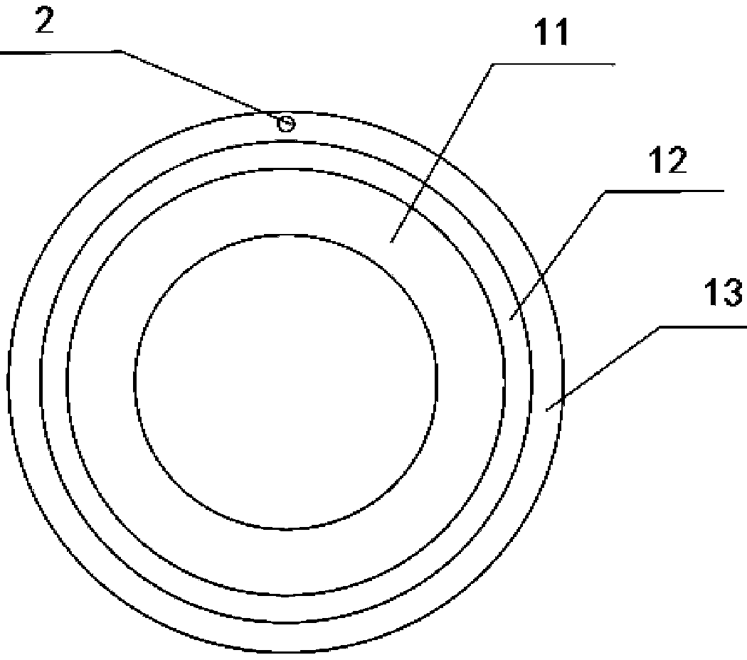
[0025] Such as figure 1 As shown, Embodiment 1 of the present invention provides a fluid transmission pipeline, which includes a non-metallic pipe body and an optical fiber sensor 2. The non-metallic pipe body includes an anti-corrosion inner pipe 11 and a protective outer pipe arranged in sequence from the inside to the outside. 13. The optical fiber sensor 2 includes an optical fiber 21 and a Faraday rotating mirror 22, the optical fiber 21 is connected to the Faraday rotating mirror 22, and the optical fiber 21 and the Faraday rotating mirror 22 are both embedded in the protective outer tube 13 .

[0026] In the embodiment of the present invention, the transmission pipeline is set as a non-metallic pipe body, which is not easy to corrode.

[0027] At the same time, the traditional form of laying the optical fiber 21 outside the pipeline is changed to implanting the optical fiber 21 into the protective outer layer inside the pipeline, which not only integrates the laying of non-m...

Embodiment 2

[0032] The optical fiber 21 of the patent and the Faraday rotating mirror 22 are both buried in the protective outer tube 13, which is achieved through the following steps:

[0033] Heat and shear and compress the thermoplastic raw materials to obtain viscous fluid raw materials;

[0034] Coating the viscous flow material on the anti-corrosion inner tube 11, and pull the optical fiber 21 and the Faraday rotating mirror 22 into the viscous flow material along the length direction of the anti-corrosion inner tube 11;

[0035] After the viscous fluid raw material is cooled, the non-metallic tube body in which the optical fiber 21 and the Faraday rotating mirror 22 are embedded is formed.

[0036] The process of embedding the optical fiber 21 in the protective outer tube 13 is: putting the thermoplastic raw material into a plastic extruder, heating and shearing and compressing the raw material to obtain the viscous fluid state raw material, the viscous fluid state is obtained through the p...

Embodiment 3

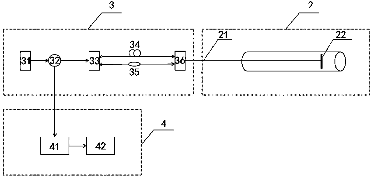
[0038] Such as figure 2 As shown, Embodiment 2 of the present invention provides a fluid transmission pipeline leakage detection system, which includes the fluid transmission pipeline provided in the above embodiments, and further includes a demodulator 3 and a signal processing terminal 4.

[0039] The demodulator 3 is connected to the optical fiber 21 and used to transmit optical signals to the optical fiber 21 and the Faraday rotator mirror 22. The optical fiber 21 and the Faraday rotator mirror 22 form an interferometer, and the demodulator 3 It is also used to receive the reflected light signal returned through the optical fiber 21 and the Faraday rotating mirror 22, the signal processing terminal 4 is connected to the demodulator 3, and the signal processing terminal 4 is used to receive the reflected light signal, And according to the reflected light signal, it is judged whether the fluid transmission pipeline leaks.

[0040] The leak detection system provided in this embo...


PUM


Abstract

The invention discloses a fluid conveying pipeline. The pipeline comprises a non-metal pipe body and an optical fiber sensor; the non-metal pipe body comprises an anti-corrosion inner pipe and a protective outer pipe which are sequentially arranged from inside to outside; the optical fiber sensor comprises an optical fiber and a Faraday rotator mirror; the optical fiber is connected with the Faraday rotator mirror; and the optical fiber and the Faraday rotator mirror are both buried in the protective outer pipe. The invention further discloses a preparation method of the fluid conveying pipeline and a fluid conveying pipeline leakage detection system. The fluid conveying pipeline leakage detection device comprises the fluid conveying pipeline, a demodulator connected with the optical fiber, and a signal processing terminal connected with the demodulator. According to the fluid conveying pipeline of the invention, the conveying pipeline is set to be the non-metal pipe body and is not prone to corrosion, meanwhile, the optical fiber is buried in the non-metal pipe body; the laying of the non-metal pipe body and the laying of the optical fiber are integrated; the optical fiber is laidin the whole length direction of the non-metal pipe body; and therefore, long-distance non-metal pipe body leakage detection can be achieved, a detection coverage rate is higher, and detection precision is higher.

Description

Technical field [0001] The invention relates to the technical field of pipeline leakage detection, in particular to a fluid transmission pipeline, a preparation method thereof, and a fluid transmission pipeline leakage detection system. Background technique [0002] With the sustained and rapid development of my country’s economy, pipeline transportation is playing an increasingly important role in the national economy, defense industry and people’s daily lives. The transportation of drinking water, natural gas, heating, oil and other resources is of great importance to the development of the national economy. Pipelines used for the transportation of various fluids have also been developed rapidly since the 1990s. [0003] In the past, steel pipe transportation was a common transportation method, and the most prominent problem of transportation steel pipe was corrosion. In order to achieve technological innovation and economic optimization, non-metallic pipes have been increasingly...

Claims


Application Information

Patent Timeline
Patent Type & Authority Applications(China)
IPC IPC(8): F16L9/12F16L58/00F17D5/06
CPCF16L9/121F16L58/00F17D5/06
Inventor 韩霞汪晗徐志军
Owner WUHAN MARINE ELECTRIC PROPULSION RES INST CHINA SHIPBUILDING IND CORP NO 712 INST
Learn More