
Automatic cleaning device for sewage treatment plant floating-flow type secondary sedimentation tank effluent weir

A sewage treatment plant, automatic cleaning technology, applied in the feeding/discharging device of the sedimentation tank, sedimentation tank, sedimentation separation and other directions, can solve the problems of affecting the sewage treatment effect, consuming a large amount of labor, and slowing the cleaning speed, saving energy Labor intensity, high cleaning efficiency, good cleaning effect

Pending Publication Date: 2020-04-17
常州市深水城北污水处理有限公司
View PDF0 Cites 0 Cited by
  • Summary
  • Abstract
  • Description
  • Claims
  • Application Information

AI Technical Summary

Problems solved by technology

The growth of moss in the effluent weir of the secondary sedimentation tank directly affects the operation of the sewage treatment system. How to effectively remove the interference of moss on the effluent water quality is a technical problem that plagues sewage treatment plants.
Most of the moss begins to grow in spring, and it adheres to the pool wall like hair in the early stage, and the color is dark green; the temperature gradually becomes suitable, and it begins to proliferate and suspend in the water at around 22°C; when the moss ages, it will become cotton wool and float on the water surface , the color is yellow-green, and it feels greasy. If it is not cleaned in time, it will block the outlet weir of the secondary sedimentation tank and affect the quality of the outlet water.
At present, the sewage treatment plant mainly cleans the moss and debris on the outlet weir of the secondary sedimentation tank manually. The cleaning speed is slow and requires a lot of labor, which affects the sewage treatment effect.

Method used


Image

  • Automatic cleaning device for sewage treatment plant floating-flow type secondary sedimentation tank effluent weir

Examples


Embodiment Construction

[0014] The specific embodiment of the present invention is further described below in conjunction with accompanying drawing:

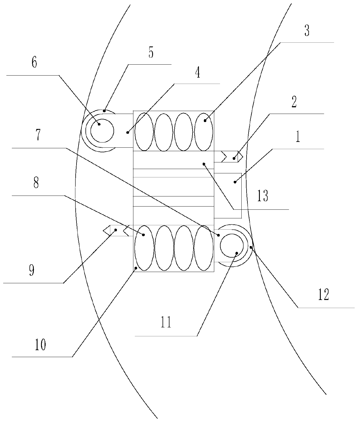
[0015] An automatic cleaning device for the outlet weir of a floating-flow secondary sedimentation tank in a sewage treatment plant, characterized in that it includes a slide table 1, a rear flushing nozzle 2, a first ultraviolet lamp tube 3, a front rotating arm 4, a front brush 5, and a front brush Motor 6, rear rotating arm 7, second ultraviolet lamp tube 8, front flushing nozzle 9, casing 10, rear brush motor 11, rear hair brush 12 and the third ultraviolet lamp tube 13, and described casing 10 is fixedly installed On the slide table 1, the first ultraviolet lamp tube 3 is fixedly installed in the installation hole on the right side of the casing 10 and the first ultraviolet lamp tube 3 is installed vertically, and the rear flushing nozzle 2 is fixed Installed in the mounting hole on the rear side of the casing 10, the front arm 4 is installed on t...


PUM


Abstract

The invention discloses an automatic cleaning device for a sewage treatment plant floating-flow type secondary sedimentation tank effluent weir. The device is characterized in that a machine shell isfixedly installed on a sliding table, a first ultraviolet lamp tube is fixedly mounted in a mounting hole, close to the right side surface, in the machine shell, a rear flushing spray head is fixedlymounted in a mounting hole in the rear side surface of the machine shell, a front rotating arm is arranged on the machine shell, a front brush motor is mounted on the front rotating arm, a front brushis mounted on the output shaft of the front brush motor, a rear rotating arm is arranged on the machine shell, a rear brush motor is installed on the rear rotating arm, a rear brush is installed on the output shaft of the rear brush motor, a front flushing spray head is installed in an installation hole in the front side surface of the machine shell, a second ultraviolet lamp tube is fixedly installed in an installation hole, close to the left side surface, in the machine shell, and the two ends of a third ultraviolet lamp tube are installed on the front side surface and the rear side surfacein the machine shell respectively. The automatic cleaning device is simple in structure, high in cleaning efficiency and good in cleaning effect, and greatly reduces the labor intensity of operators.

Description

technical field [0001] The invention belongs to the technical field of sewage treatment, and in particular relates to an automatic cleaning device for an outlet weir of a floating-flow secondary settling tank in a sewage treatment plant. Background technique [0002] Sewage treatment is the process of purifying sewage to meet the water quality requirements of a certain water body for drainage or reuse. Sewage treatment is widely used in various fields such as construction, agriculture, transportation, energy, petrochemical, environmental protection, urban landscape, medical treatment, catering, etc., and it is also increasingly entering the daily life of ordinary people. The secondary settling tank is an important part of the activated sludge system. Its main function is to separate the sludge, clarify the mixed solution, concentrate and return the activated sludge. Its working effect can directly affect the effluent water quality and return sludge concentration of the acti...

Claims


Application Information

Patent Timeline
IPC IPC(8): B01D21/00B01D21/24
CPCB01D21/0006B01D21/2444
Inventor 郑培庞诚陆桂勇刘礼祥王云辉戴泳陈哲刘毅杨建卫周文伟刘文燕曹洪钧杨观乐
Owner 常州市深水城北污水处理有限公司
Learn More