Eureka AIR delivers breakthrough ideas for toughest innovation challenges, trusted by R&D personnel around the world.

A liquid slag waste heat recovery system

A waste heat recovery system and liquid slag technology, applied in the direction of recycling technology, can solve the problems of lack of recovery technology, etc., and achieve the effect of improving sufficient heat exchange, improving the ability of emergency response to accidents, and improving heat exchange efficiency

Active Publication Date: 2021-07-13
XI AN JIAOTONG UNIV
View PDF4 Cites 0 Cited by
  • Summary
  • Abstract
  • Description
  • Claims
  • Application Information

AI Technical Summary

Problems solved by technology

For the liquid slag of the above-mentioned high-quality waste heat resources, there is currently a lack of perfect recovery technology, and the potential for waste heat recovery is huge

Method used


Image

  • A liquid slag waste heat recovery system
  • A liquid slag waste heat recovery system
  • A liquid slag waste heat recovery system

Examples


Embodiment approach

[0066] a) Open the flue gas outlet gap around the top of the granulation bin, the flue gas flows into the flue gas annular header through the flue gas outlet gap around the granulation bin, and finally set up a collection flue on the flue gas annular header to draw out the flue gas .

[0067] b) Open the flue gas outlet gap around the slag discharge pipe in the center of the granulation bin, the flue gas flows into the flue gas annular header through the flue gas outlet gap in the center of the granulation bin, and finally set up a collection flue on the flue gas annular header to lead out smoke.

[0068] In the connecting section between the moving bed waste heat recovery device and the granulation rotor, a slag cotton scraper is installed. The slag cotton scraper is arranged on both sides of the granulation rotor, arranged at 180°, designed according to the sawtooth structure, and adopts 310S stainless steel for high temperature resistance material. In the early stage of w...


PUM


Abstract

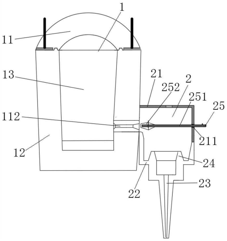
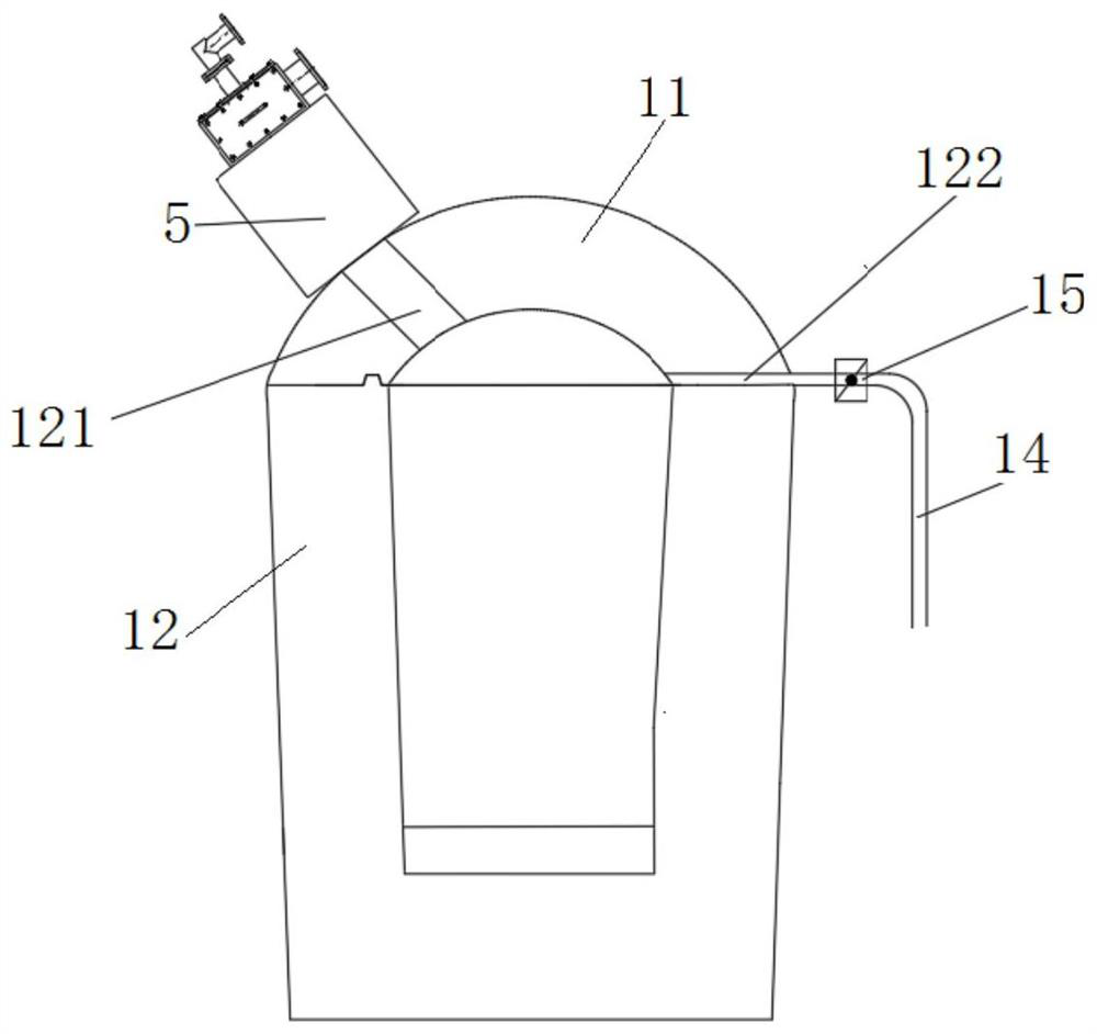
The invention discloses a liquid slag waste heat recovery system, which comprises a slag buffer device, a flow control device, a centrifugal granulation device and a moving bed device; one end of the slag buffer device is connected to a slag ditch, and the other end of the slag buffer device It is connected to the inlet end of the flow control device, the outlet end of the flow control device is connected to the inlet end of the centrifugal granulation device, and the outlet end of the centrifugal granulation device is connected to the moving bed device; the present invention effectively avoids the The impact of blast furnace intermittent slag discharge on the centrifugal granulation system ensures the stable operation of the centrifugal granulation system and improves the emergency response capability of the waste heat recovery system; through the installation of flow control devices, centrifugal granulation devices and moving bed devices, effective It improves the sufficient heat exchange of slag particles and the smooth discharge of the system, and effectively improves the heat exchange efficiency.

Description

technical field [0001] The invention relates to the technical field of blast furnace slag waste heat recovery, in particular to a liquid slag waste heat recovery system. Background technique [0002] In the metallurgical industry, such as iron and steel smelting, a large amount of high-temperature slag is produced, and the slag temperature of blast furnace slag can reach 1400-1550 ° C; my country's existing iron and steel smelting technology will produce 0.3 tons of blast furnace slag for every ton of pig iron produced. In 2016, my country's pig iron Calculating the output of 700 million tons, it can be equivalent to producing more than 210 million tons of blast furnace slag. For the liquid slag of the above-mentioned high-quality waste heat resources, there is currently a lack of perfect recovery technology, and the potential for waste heat recovery is huge. [0003] Compared with the water quenching method, the dry method not only saves a lot of water resources, but also h...

Claims


Application Information

Patent Timeline
Patent Type & Authority Patents(China)
IPC IPC(8): C21B3/08C21B3/06
CPCC21B3/06C21B3/08C21B2400/05C21B2400/08Y02W30/50
Inventor 王树众吴志强马琛赵军肖照宇李美全徐宁文
Owner XI AN JIAOTONG UNIV
Why Eureka
Eureka Blog
Learn More