Pressure-equalization energy recovery system for blast-furnace hot-blast stoves, and use method of system

A technology of energy recovery and hot blast stove, which is applied to blast furnaces, blast furnace details, blast furnace parts, etc., can solve problems affecting blast furnace production, energy waste, and large fluctuations in cold air pressure, achieving good economic and social effects and reducing costs , the effect of simple structure

Inactive Publication Date: 2020-04-17
HUATIAN ENG & TECH CORP MCC
View PDF5 Cites 3 Cited by
  • Summary
  • Abstract
  • Description
  • Claims
  • Application Information

AI Technical Summary

Problems solved by technology

If the hot blast stove in the high-pressure air supply state is switched to the air supply state, the high-pressure gas in the hot blast stove needs to be unloaded, usually directly emptied through the chimney, resulting in a waste of energy
If the hot blast stove in the firing state is turned into the air supply state, the pressure in the hot blast stove needs to be raised first. Usually, cold air is used to pressurize the hot blast stove, resulting in large fluctuations in the pressure of the cold blast, which affects the production of the blast furnace.

Method used


Image

  • Pressure-equalization energy recovery system for blast-furnace hot-blast stoves, and use method of system

Examples


Embodiment 1

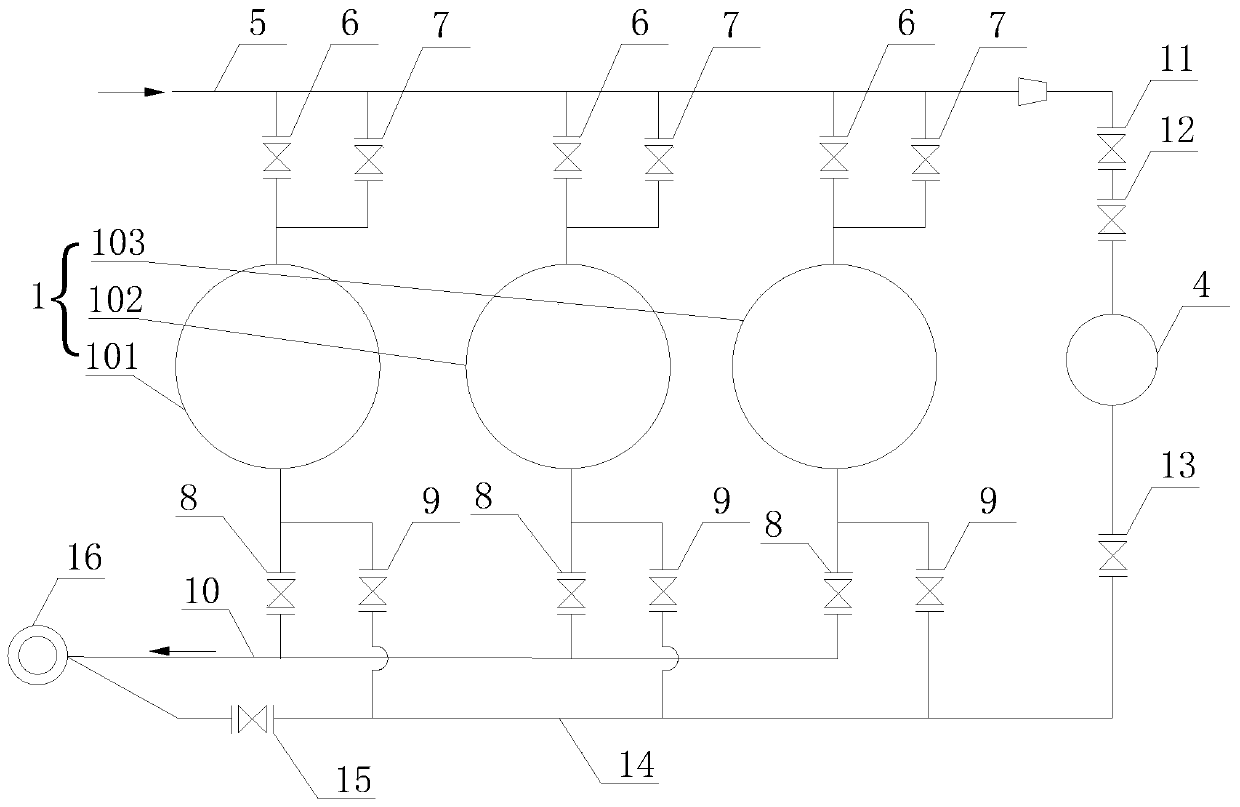
[0024] The present invention is a pressure equalization energy recovery system for blast furnace hot blast stoves, which includes several hot blast stoves 1, residual pressure recovery tanks 4, cold air pipes 5, flue gas pipes 10, pressure discharge pipes 14 and chimneys 16; several hot blast stoves 1 A cold air cut-off valve 6 and a cold air pressure equalizing valve 7 are arranged in parallel between the inlet of the cold air pipe 5 and the pipe, and a smoke cut-off valve 8 is arranged between the outlet and the flue gas pipe 10 through pipes, and the outlet and the exhaust pressure A cold air pressure relief valve 9 is arranged through a pipeline between the pipes 14; a pressure regulating valve 11 and a pressure filling valve 12 are arranged through a pipeline between the inlet of the residual pressure recovery tank 4 and the cold air pipeline 5, and the outlet and the pressure relief valve 12 are arranged through the pipeline. A pre-pressure equalization valve 13 is provid...

Embodiment 2

[0030]A method for using a pressure equalizing energy recovery system for blast furnace hot blast stoves described in Embodiment 1, one of the several hot blast stoves 1 is in the air supply state, and the other hot blast stoves 1 are in the firing state; the hot blast in the air supply state The furnace 1 is in a high-pressure state, the cold air cut-off valve 6 and the cold air pressure equalizing valve 7 at its inlet are respectively open and closed, the flue gas cut-off valve 8 and the cold air pressure relief valve 9 at its outlet are both in a closed state, and the high-pressure cold air passes through The cold blast pipe 5 and the cold blast cut-off valve 6 enter the hot blast stove 1 to be heated and then sent to the blast furnace for utilization; In the closed state, the cold air pressure relief valve 9 and the flue gas cut-off valve 8 at the outlet are respectively in the closed and open states, and the flue gas produced by the combustion of these hot blast stoves 1 i...

Embodiment 3

[0037] Such as figure 1 As shown, a kind of pressure equalization energy recovery system for blast furnace hot blast stove of the present invention is characterized in that it includes several hot blast stoves 1, residual pressure recovery tank 4, cold air pipeline 5, flue gas pipeline 10, pressure discharge pipe 14 and chimney 16; This embodiment takes three hot blast stoves 1 as an example for illustration, these three hot blast stoves are No. 1 hot blast stove 101, No. 2 hot blast stove 102 and No. 3 hot blast stove 103; Between the inlet of No. hot blast stove 102 and No. three hot blast stove 103 and the cold wind pipeline 5, a cold wind cut-off valve 6 and a cold wind equalizing valve 7 are arranged in parallel through pipelines. The outlet of No. hot blast stove 103 and the flue gas pipeline 10 are all provided with a flue gas shut-off valve 8 through the pipeline, and the outlets of the No. 1 hot blast stove 101, No. A cold air pressure relief valve 9 is provided thro...


PUM


Abstract

The invention discloses a pressure-equalization energy recovery system for blast-furnace hot-blast stoves. The pressure-equalization energy recovery system for the blast-furnace hot-blast stoves comprises a plurality of the hot-blast stoves, a waste pressure recovery tank, a cold air pipeline, a smoke pipeline, a pressure relief pipe and a chimney, wherein a cold air stop valve and a cold air pressure-equalization valve are arranged between each of inlets of the plurality of hot-blast stoves and the cold air pipeline in parallel, a smoke stop valve is arranged between each of outlets of the plurality of hot-blast stoves and the smoke pipeline, and a cold air pressure relief valve is arranged between each of the outlets of the plurality of hot-blast stoves and the pressure relief pipe; a pressure-charging adjustment valve and a pressure-charging valve are arranged between an inlet of the waste pressure recovery tank and the cold air pipeline, and a pressure-pre-equalization valve is arranged between an outlet of the waste pressure recovery tank and the pressure relief pipe; and the smoke pipeline and an outlet end of the pressure relief pipe communicate with the chimney separately,and a main pressure relief valve is further arranged at the outlet end of the pressure relief pipe. The invention further discloses a use method of the recovery system. According to the pressure-equalization energy recovery system for the blast-furnace hot-blast stoves, during application, waste pressure during pressure relief of the hot-blast stoves can be recovered, the fluctuation of a cold airpressure during pressure-charging of the hot-blast stoves can further be reduced, and no power consumption during daily maintenance is achieved; and moreover, a more obvious effect is achieved in thecase of higher capacity of the waste pressure recovery tank.

Description

technical field [0001] The invention relates to the technical field of iron and steel metallurgy, energy saving and environmental protection, and more specifically relates to a hot blast stove system for ironmaking blast furnaces, in particular to a pressure equalization energy recovery system for blast furnace hot blast stoves and a method for using the same. Background technique [0002] At present, the blast furnace is generally equipped with three hot blast stoves, and generally adopts the working system of two firing and one delivery, that is, two hot blast stoves are in the firing state, and one hot blast stove is in the air supply state. Turn the hot blast stove that has been fired into the air supply state, and then turn the hot blast stove that has finished the air supply into the furnace state. The hot blast stove has been in this periodic alternate conversion state. When the hot blast stove is blowing air, the hot blast stove is in a high pressure state, and when ...

Claims


Application Information

Patent Timeline
Patent Type & Authority Applications(China)
IPC IPC(8): C21B9/00
CPCC21B9/00C21B2100/64Y02P10/20
Inventor 黄东升陈冬文冰洁
Owner HUATIAN ENG & TECH CORP MCC
Why Eureka
Try Eureka