W flame boiler adopting turbulent burners

A technology of swirl burner and pulverized coal burner, which is applied to burners, burners for burning powder fuel, combustion methods, etc. The effect of improving the combustion characteristics and improving the flexible peak shaving ability

Active Publication Date: 2020-04-17
HARBIN INST OF TECH
View PDF12 Cites 2 Cited by
  • Summary
  • Abstract
  • Description
  • Claims
  • Application Information

AI Technical Summary

Problems solved by technology

The actual operation results show that: for the W-flame boiler using the swirl pulverized coal burner, the maximum peak-shaving capability of the boiler is about 50% when the ordinary micro-oil ignition method is used, which is far from meeting the government's requirements for the flexible peak-shaving capability of power plant boilers. 20% required

Method used


Image

  • W flame boiler adopting turbulent burners
  • W flame boiler adopting turbulent burners
  • W flame boiler adopting turbulent burners

Examples


specific Embodiment approach 1

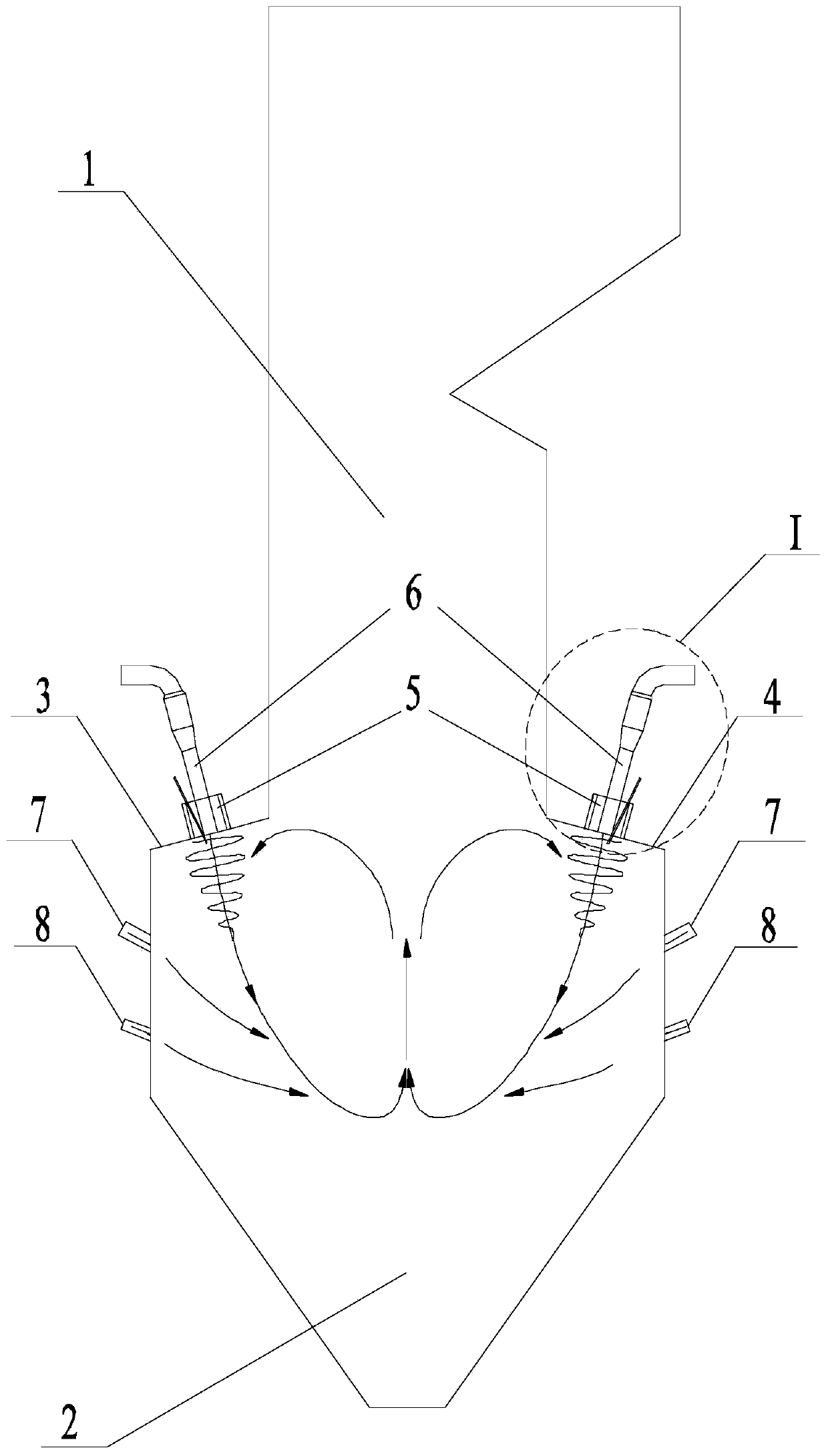
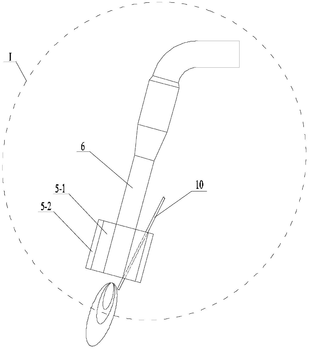
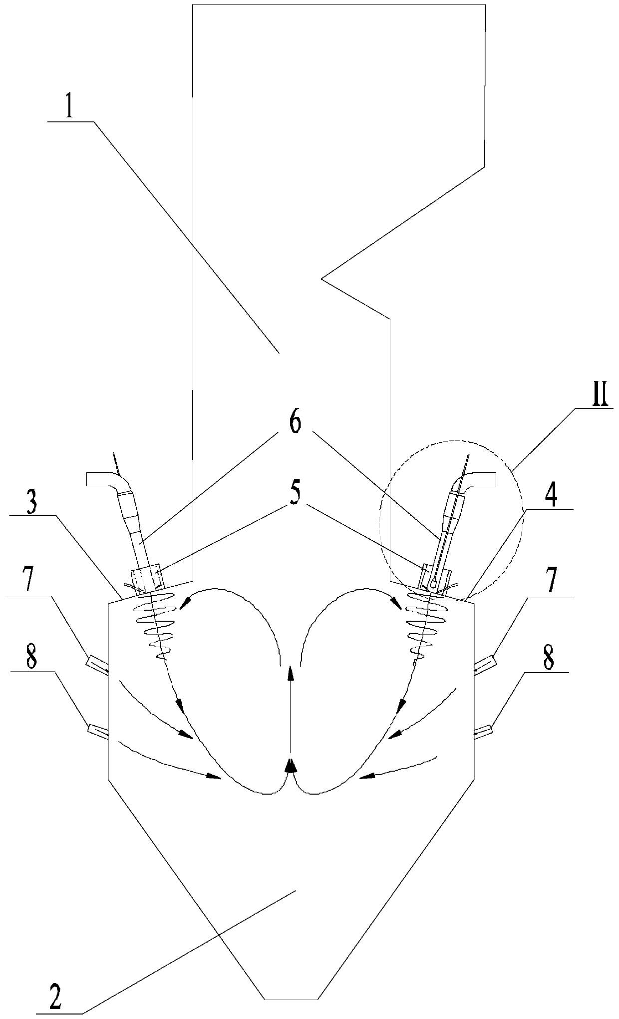
[0025] Specific implementation mode one: combine Figure 3-Figure 5 Describe this embodiment, a W-flame boiler using a swirl burner described in this embodiment, which includes an upper furnace 1, a lower furnace 2, a front furnace arch 3, a rear furnace arch 4, a front wall, a rear wall and a plurality of Swirl pulverized coal burner 5; swirl pulverized coal burner 5 includes adjustable cone rod 9, micro oil ignition gun 10 and diversion cone 11, upper furnace 1, front furnace arch 3, front wall, lower furnace 2 , the rear wall and the rear furnace arch 4 constitute the furnace body, the micro-oil ignition gun 10 is installed in the adjustable cone pull rod 9, and the bottom end of the adjustable cone pull rod 9 is fixedly installed in the diversion cone 11, and the adjustable cone pull rod 9. The micro-oil ignition gun 10 and the guide cone 11 are installed in the shell of the swirl pulverized coal burner 5, and the swirl pulverized coal burner 5 is installed on the water wa...

specific Embodiment approach 2

[0026]Specific implementation mode two: combination Figure 3-Figure 5 Describe this embodiment, a W flame boiler using a swirl burner described in this embodiment, a plurality of swirl pulverized coal burners 5 on the water wall of the front furnace arch 3 are arranged in a straight line, and the water wall of the rear furnace arch 4 A plurality of swirl pulverized coal burners 5 on the top are arranged in a straight line, and other methods are the same as in the first embodiment.

specific Embodiment approach 3

[0027] Specific implementation mode three: combination Figure 3-Figure 5 Describe this embodiment, a W flame boiler using a swirl burner described in this embodiment, the swirl pulverized coal burner 5 also includes a swirl inner secondary air nozzle 5-1, a swirl outer secondary air nozzle 5 -2 and dense coal powder nozzle 6, dense coal powder nozzle 6, inner secondary air nozzle 5-1 and swirling outer secondary air nozzle 5-2 are arranged coaxially from the inside to the outside in sequence. A thick pulverized coal spout 6, an inner secondary air spout 5-1 and a swirling outer secondary air spout 5-2 are all connected with the water wall of the front furnace arch 3, and each dense pulverized coal spout 6 on the water wall of the back furnace arch 4 , the inner secondary air nozzle 5-1 and the swirl outer secondary air nozzle 5-2 are all connected to the rear furnace arch 4 water wall, and the adjustable cone rod 9 is inserted into the concentrated coal powder through the sle...


PUM


Abstract

The invention discloses a W flame boiler adopting turbulent burners, relates to a power station boiler adopting a flexible peak shaving technology, and belongs to the field of boilers. The invention aims to solve the problem that the W flame boiler adopts the turbulent pulverized coal burners in the prior art, the maximum peak shaving capacity of a boiler with a common micro-oil ignition mode is about 50%, the requirement of the government on the flexible peak shaving capacity of the power station boiler cannot be met; the W flame boiler adopting the turbulent burners comprises an upper hearth, a lower hearth, a front furnace arch, a rear furnace arch, a front wall, a rear wall and a plurality of turbulent pulverized coal burners, each turbulent pulverized coal burner comprises an adjustable cone pulling rod, a micro oil ignition gun and a flow guide cone, wherein the micro oil ignition guns are installed in the adjustable cone pulling rods, the bottom ends of the adjustable cone pulling rods are fixedly installed in the flow guide cones, the adjustable cone pulling rods, the micro oil ignition guns and the flow guide cones are installed in shells of the turbulent pulverized coal burners, and the turbulent pulverized coal burners are installed on a front furnace arch water wall and a rear furnace arch water wall correspondingly.

Description

technical field [0001] The invention relates to a power station boiler using flexible peak regulation technology, in particular to a W flame boiler using a swirl burner. Background technique [0002] In recent years, with the intervention of large-scale renewable energy, China's power system has undergone tremendous changes. Renewable energy generation capacity is taking an increasing share in the grid. However, due to the limitations of the power generation method itself, the output instability of renewable energy power generation poses a huge challenge to the regulation capability of the power system; in addition, a large number of uncertain factors on the power generation side and the demand side also affect the security and stability of the power system run. Statistics show that in 2015, China's annual net thermal power installed capacity was 72.02 million kilowatts (including 51.86 million kilowatts of coal-fired power), which was the largest annual production since 2...

Claims


Application Information

Patent Timeline
Patent Type & Authority Applications(China)
IPC IPC(8): F23C7/00F23D1/02F23K3/02F23L7/00
CPCF23C7/002F23D1/02F23K3/02F23L7/007Y02E20/34
Inventor 李争起杜贺郑智巍刘文杰曾令艳陈智超
Owner HARBIN INST OF TECH
Why Eureka
Try Eureka