Drying waste heat reutilizing integration device

A waste gas and dryer technology, applied in heating devices, drying, dryers, etc., can solve the problems of imperfect heat recovery equipment, less heat recovery, environmental pollution, etc., to achieve good environmental protection, high degree of automation, application wide range of effects

Active Publication Date: 2020-04-17
青岛创客智造机械设备有限公司
View PDF7 Cites 3 Cited by
  • Summary
  • Abstract
  • Description
  • Claims
  • Application Information

AI Technical Summary

Problems solved by technology

[0004] The present invention mainly aims at the problems that the heat and moisture generated in the above drying process can only recover part of the heat, the recovered heat is less, the heat recovery equipment is not perfect, the heat is wasted and the environment is polluted, and a new type of drying waste heat reuse is provided. The integrated device compresses all the hot and humid gas including saturated steam and returns it to the dryer, which realizes the recycling of energy, has a high degree of automation, a wide range of applications, and is environmentally friendly

Method used


Image

  • Drying waste heat reutilizing integration device
  • Drying waste heat reutilizing integration device

Examples


Embodiment 1

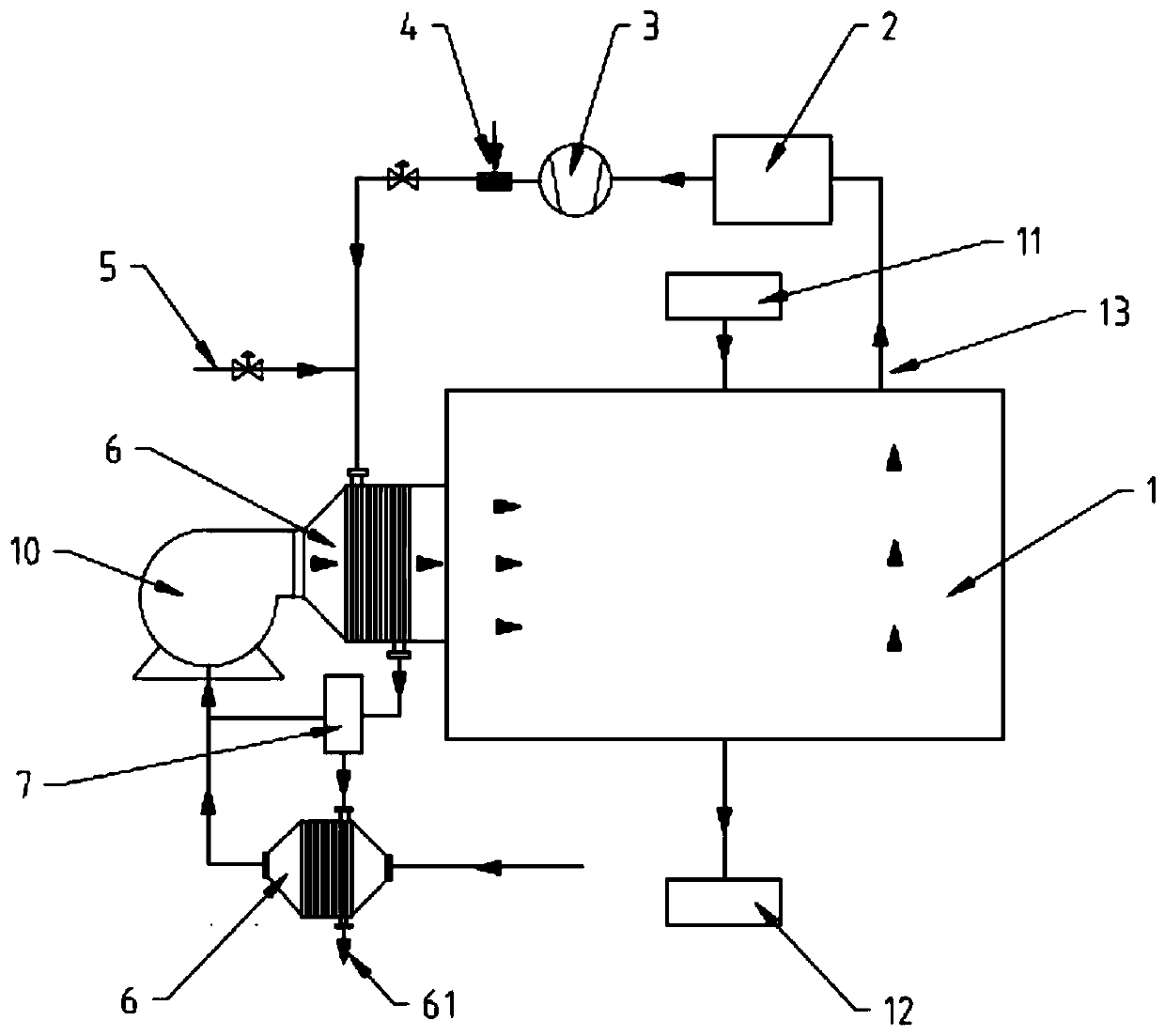
[0036] see figure 1 , figure 1 It is a structural schematic diagram of an integrated device for drying waste heat reuse in this embodiment, including a dryer 1, a media processor 2, a compressor 33, a shower 4 and a heat exchanger 6, and the upper part of the dryer 1 is provided with a material The inlet 11 and the waste gas outlet 13 are provided with a material outlet 12 at the lower part, and the high-temperature hot steam is discharged from the waste gas outlet 13 after drying the materials in the dryer 1 . The dryer 1 includes commonly used box dryers, vertical dryers, etc., which can dry all materials with a moisture content of 0-100%, and the moisture content of the dried materials can be between 0-100%. adjust.

[0037] Further, one end of the waste gas outlet 13 is connected to a media processor 2, and a filter is provided in the media processor 2, which can filter impurities in the waste gas. The media processor 2 includes but not limited to the following types: cy...

Embodiment 2

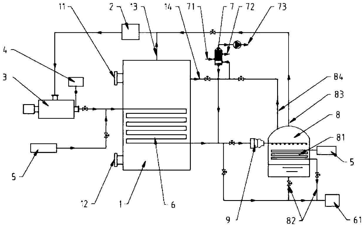
[0048] In Example 1, the heat exchanger 6 is externally connected to the dryer 1. In this example, the heat exchanger 6 is embedded in the dryer 1, which is realized by connecting the secondary steam recovery unit behind the heat exchanger 6. Recycling of hot steam.

[0049] Combine below figure 2 , the secondary steam recovery unit in this embodiment includes a flash tank 8 , and the heat exchanger 6 is connected to the flash tank 8 through a steam condensate pipe 61 . Preferably, a supercharger 9 is also connected between the steam condensate pipeline 61 and the flash tank 8, and the supercharger 9 introduces the hot steam in the steam condensate pipeline 61 into the flash tank 8 after pressurization .

[0050] Further, the flash tank 8 is provided with a coil heat exchanger 81, and the heat transfer medium such as steam, hot water, or heat transfer oil is passed through the coil heat exchanger 81. After entering the flash tank 8, the high-pressure saturated water become...


PUM


Abstract

The invention provides a drying waste heat reutilizing integration device which comprises a drying device (1), a medium treating device (2), a compressor (3), a sprayer (4) and a heat exchanger (6). Awaste gas outlet (13) is formed in the upper portion of the drying device (1). One end of the waste gas outlet (13) is connected with the medium treating device (2). The rear of the medium treating device (2) is connected with the compressor (3). The compressor (3) is connected with the heat exchanger (6) through a pipeline. The outlet end of the compressor (3) is connected with the sprayer (4).A starting heat source (5) is connected to a pipeline between the sprayer (4) and the heat exchanger (6). The heat exchanger (6) is connected with the drying device (1). According to the system, hot wet gas exhausted by the waste gas outlet (13) returns to the drying device again after being compressed, recycling of energy is achieved, the automation degree is high, and the device is environmentally friendly.

Description

technical field [0001] The invention relates to a new technology of energy saving and environmental protection in the field of drying technology, in particular to an integrated device for recycling waste heat from drying. Background technique [0002] In the current drying process, the moisture in the material is vaporized and escaped by drying the material to obtain a solid material with a specified moisture content. In this process, a large amount of waste gas (hot moisture) is produced, and the waste gas contains a large amount of latent heat. If the waste gas is directly discharged into the air, it will not only pollute the atmospheric environment, but also cause a lot of waste of energy. In the prior art, some heat is recovered by spraying or heat exchange. For example, the patent number is CN 202709697U, and the name is heat recovery device for exhaust gas discharged from boiling drying equipment. A heat recovery device is provided. A heat exchange surface is provided...

Claims


Application Information

Patent Timeline
Patent Type & Authority Applications(China)
IPC IPC(8): F26B23/00F26B25/00
CPCF26B23/002F26B25/007Y02P70/10
Inventor 李永兆李斌杰
Owner 青岛创客智造机械设备有限公司
Why Eureka
Try Eureka