
Method for monitoring depth of groove

A groove depth and groove technology, applied in the direction of measuring devices, instruments, electrical components, etc., can solve the problems of long slicing time, low efficiency of measuring super-junction grooves, and high detection costs, so as to improve yield and avoid product The effect of scrapping and saving production cost

Inactive Publication Date: 2020-04-17
HUA HONG SEMICON WUXI LTD
View PDF2 Cites 2 Cited by
  • Summary
  • Abstract
  • Description
  • Claims
  • Application Information

AI Technical Summary

Problems solved by technology

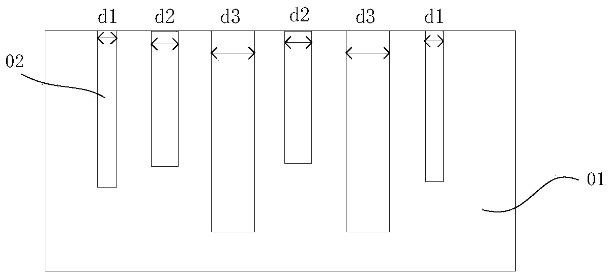
[0006] In view of the shortcomings of the prior art described above, the purpose of the present invention is to provide a method for monitoring trench depth, which is used to solve the problem of low efficiency and high detection cost of measuring super junction trenches caused by long slicing time in the prior art question

Method used


Image

  • Method for monitoring depth of groove
  • Method for monitoring depth of groove
  • Method for monitoring depth of groove

Examples


Embodiment Construction

[0021] Embodiments of the present invention are described below through specific examples, and those skilled in the art can easily understand other advantages and effects of the present invention from the content disclosed in this specification. The present invention can also be implemented or applied through other different specific implementation modes, and various modifications or changes can be made to the details in this specification based on different viewpoints and applications without departing from the spirit of the present invention.

[0022] see Figure 1 to Figure 4 . It should be noted that the diagrams provided in this embodiment are only schematically illustrating the basic idea of ​​the present invention, and only the components related to the present invention are shown in the diagrams rather than the number, shape and shape of the components in actual implementation. Dimensional drawing, the type, quantity and proportion of each component can be changed arb...


PUM


Abstract

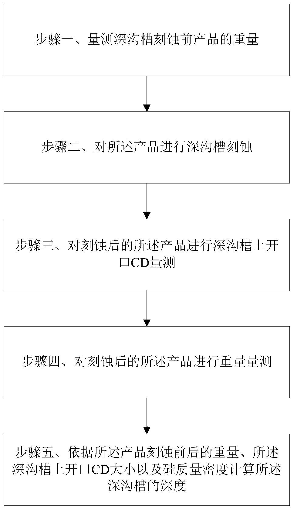
The invention provides a method for monitoring the depth of a groove. The method comprises the following steps: measuring the weight of a product before groove etching; carrying out groove etching onthe product; measuring an opening CD on the groove of the etched product; measuring the weight of the etched product; and calculating the depth of the groove according to the weight of the product before and after etching, the size of the opening CD on the groove and the silicon mass density. The online monitoring of the product after the trench etching process can be effectively realized, the real-time online monitoring effect is achieved, the product scrap is effectively avoided, the yield is improved, and the production cost is saved.

Description

technical field [0001] The invention relates to the field of semiconductor manufacturing, in particular to a method for monitoring the depth of a trench. Background technique [0002] The remarkable feature of power devices, especially super junction devices, is that the depth of the etched trench can reach more than 40um, and the aspect ratio is close to 10:1 to form a PIN diode structure, so that the electric field distribution in the drift region is very uniform, and the durability of the device is improved. pressure capacity. However, semiconductor equipment suppliers currently do not have good measurement equipment for this deep process, and it is still a blind spot for online monitoring in the normal production process. [0003] Most foundries that produce power devices in the industry currently use sampling for slicing (TEM) analysis to confirm whether the stability of the machine and the depth of the trench meet the process requirements. The commonly used sampling f...

Claims


Application Information

Patent Timeline
Patent Type & Authority Applications(China)
IPC IPC(8): H01L21/66G01B21/18
CPCH01L22/12H01L22/20G01B21/18
Inventor 张召金新
Owner HUA HONG SEMICON WUXI LTD
Learn More