Portable magneto-rheological flexible clamping device and clamping method

A flexible clamping and magnetorheological technology, applied in the field of mechanical processing and clamping, can solve the problems of affecting the processing accuracy, the decrease of the fatigue strength of the blade, and the influence of the tool processing track, so as to improve the processing efficiency, ensure the processing accuracy, and improve the clamping method. quick effect

Active Publication Date: 2020-04-21
DALIAN UNIV OF TECH
View PDF6 Cites 17 Cited by
  • Summary
  • Abstract
  • Description
  • Claims
  • Application Information

AI Technical Summary

Problems solved by technology

However, there are some problems with this method: first, the low-melting-point alloy vapor is toxic, which affects health and pollutes the environment; second, the bismuth element in the low-melting-point alloy penetrates into the blade, resulting in a decrease in the fatigue strength of the blade, which easily induces blade fracture; third, the cast alloy The blade needs to be removed before pouring, and the fixture needs to be clamped twice with the workbench after pouring, resulting in positioning error and affecting the machining accuracy
However, the details of the application of the external magnetic field are not explained. In actual processing, the external magnetic field may affect the machining trajectory of the tool.
In 2015, Zhang Dinghua et al. invented a flexible support device in the patent CN201510046697.0. The lower part of the blade body is immersed in magnetorheology, and the flexible support is implemented through external excitation, which can meet the clamping process of the upper part of the blade body. required, but subsequent cleaning treatment is required

Method used


Image

  • Portable magneto-rheological flexible clamping device and clamping method
  • Portable magneto-rheological flexible clamping device and clamping method
  • Portable magneto-rheological flexible clamping device and clamping method

Examples


Embodiment Construction

[0013] The specific implementation manner of the present invention will be described in detail in conjunction with the accompanying drawings and technical solutions.

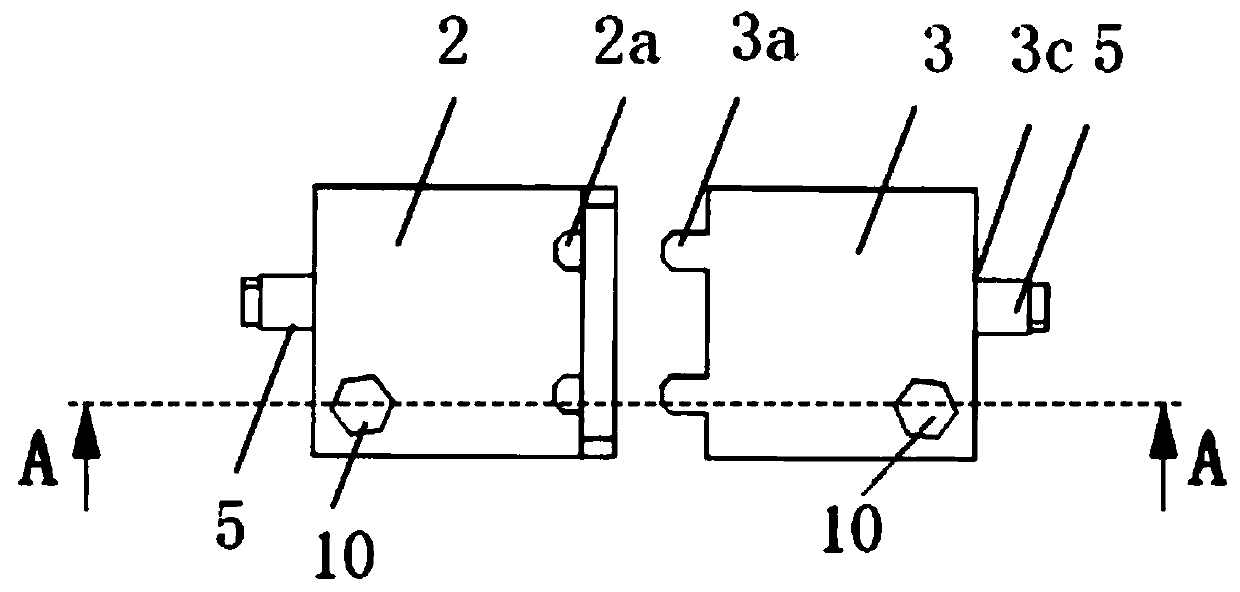
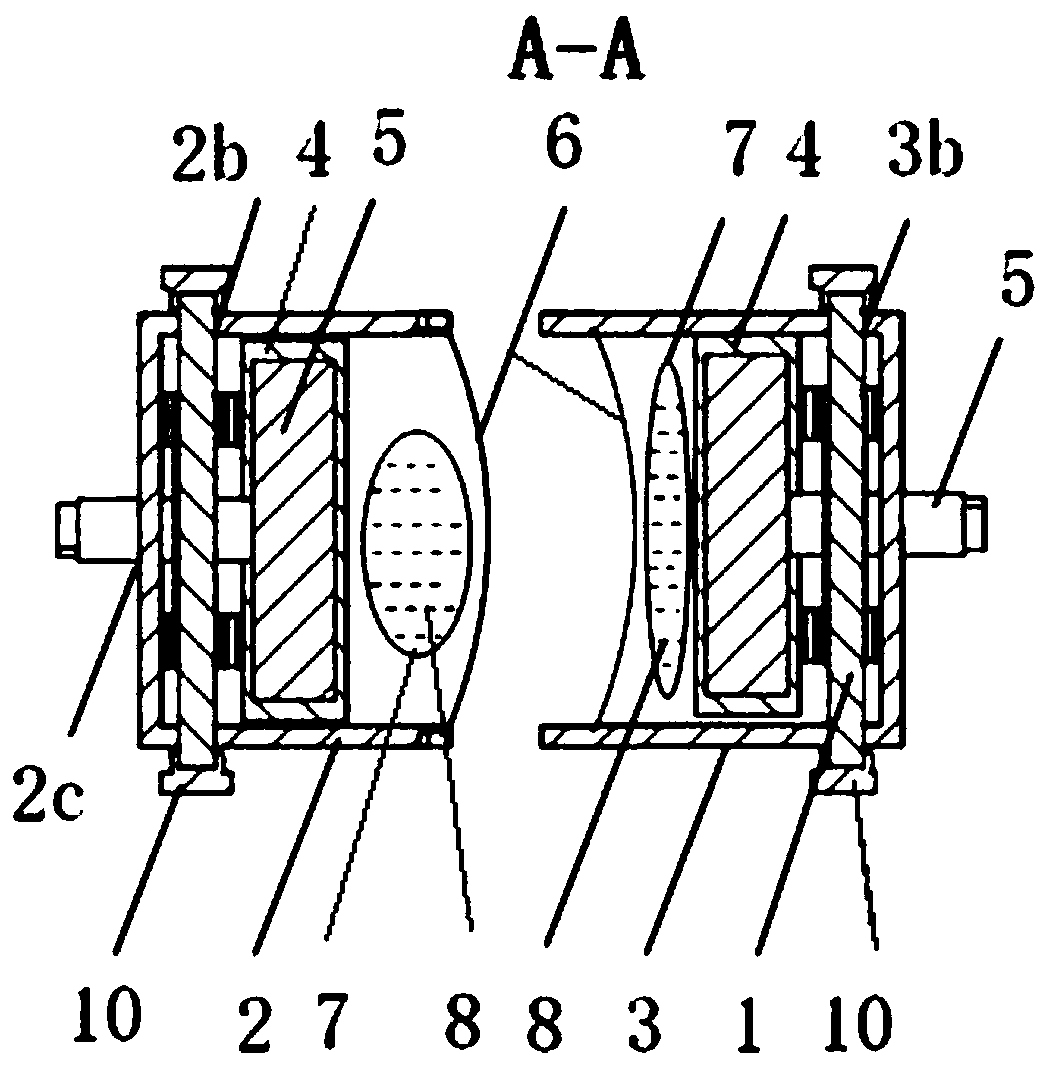
[0014] The blade 9 is made of high-temperature alloy GH4196 sheet material, the thickness after rolling is 0.8mm, the total length of the blade is 80mm, the final surface roughness is 0.4, and the minimum tolerance of the blade body profile is +0.03~-0.03mm. Carbonyl iron powder magnetorheological fluid is made of 40% volume fraction of carbonyl iron powder and 60% volume fraction of silicone oil, with a density of 3.55g / ml. The maximum thickness of magnetorheological fluid is 10mm. Grinding force 100N. The magnetic field strength is greater than 120A / m.

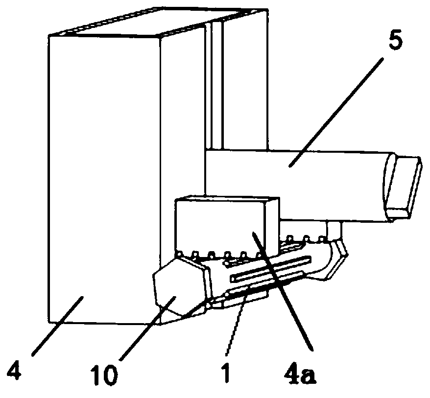
[0015] The portable magneto-rheological flexible clamping device designed in the present invention is composed of a male mold assembly and a female mold assembly, and the internal structures of the two sets of assemblies are the same. In the punch assembly,...


PUM


Abstract

The invention discloses a portable magneto-rheological flexible clamping device and method, belongs to the technical field of machining clamping, and relates to the portable magneto-rheological flexible clamping device and method. The device is composed of a convex die and a concave die. The clamping method comprises the steps that firstly, the concave die and the convex die are placed on two sides of a blade so that the concave die and the convex die are matched; a magnetorheological fluid storage bag is extruded by a piston so that an elastic soft film expands and extends to be tightly attached to a blade body; a long switch permanent magnet is turned on, an excitation magnetic field is applied, a magnetorheological fluid is excited and solidified, and reliable clamping of the blade is achieved; and after the blade is machined, the magnetic field of the long switch permanent magnet is closed, a clamping force is removed, and the blade is taken out. A shell type piston is adopted to extrude the magnetorheological fluid storage bag to make the soft film be rapidly attached to the blade so as to achieve rapid positioning of the blade, the magnetorheological fluid in the soft film israpidly solidified through controllable excitation and works in an extrusion mode, and supporting rigidity and reliability are guaranteed. And on the basis of avoiding secondary clamping, machining efficiency is improved, and machining precision is guaranteed.

Description

technical field [0001] The invention belongs to the technical field of machining and clamping, and relates to a portable magnetorheological flexible clamping device and a clamping method. Background technique [0002] Thin-walled parts are important parts of aviation gas turbine engines. Reliable clamping of thin-walled parts represented by blades is the core link to ensure efficient material removal and final machining geometric accuracy of parts. The blade machining process requires reliable blade clamping, and the suspended area should be minimized to prevent vibration deformation. Generally, blades cannot be directly clamped by claws, and blades are thin-walled workpieces. Due to poor rigidity, vibration deformation, force deformation, heat deformation, etc. are easy to occur during processing, and their shape and size tolerances cannot be guaranteed. The primary technical problem faced in processing is the blade clamping scheme. At present, for the processing of blade...

Claims


Application Information

Patent Timeline
Patent Type & Authority Applications(China)
IPC IPC(8): B23Q3/08
CPCB23Q3/065B23Q3/086
Inventor 刘海波王俊鹏罗祺李特薄其乐刘阔王永青
Owner DALIAN UNIV OF TECH
Why Eureka
Try Eureka