
Magnetic field assisted ultra-precise machining device and method

An ultra-precision machining, magnetic field-assisted technology, used in positioning devices, metal processing equipment, metal processing machinery parts, etc., can solve the problems of difficult ultra-precision machining, poor surface quality of workpieces, poor thermal conductivity, etc., to reduce the expansion/recovery effect. , The effect of improving the quality of the machined surface and excellent surface roughness

Inactive Publication Date: 2020-04-21
HUAZHONG UNIV OF SCI & TECH
View PDF5 Cites 2 Cited by
  • Summary
  • Abstract
  • Description
  • Claims
  • Application Information

AI Technical Summary

Problems solved by technology

These materials show processing problems such as high processing hardness, large cutting force, high cutting temperature, severe tool wear, low processing efficiency, and unsatisfactory processing quality during processing, which are typical difficult-to-machine materials.
Ultra-precision diamond cutting is widely used in the processing of optical-grade surface precision parts, but it is very difficult to directly perform ultra-precision machining on the above-mentioned difficult-to-machine materials. The thermal conductivity of the above-mentioned materials is poor. When performing ultra-precision single-point diamond turning, the tool tip and The material in the contact area of ​​the workpiece will form a local high temperature due to the accumulation of cutting heat, which will turn the material into a molten viscous fluid, which will seriously stick to the knife, resulting in poor surface quality of the workpiece after machining and serious tool wear

Method used


Image

  • Magnetic field assisted ultra-precise machining device and method

Examples


Embodiment Construction

[0027] In order to make the object, technical solution and advantages of the present invention clearer, the present invention will be further described in detail below in conjunction with the accompanying drawings and embodiments. It should be understood that the specific embodiments described here are only used to explain the present invention, not to limit the present invention. In addition, the technical features involved in the various embodiments of the present invention described below can be combined with each other as long as they do not constitute a conflict with each other.

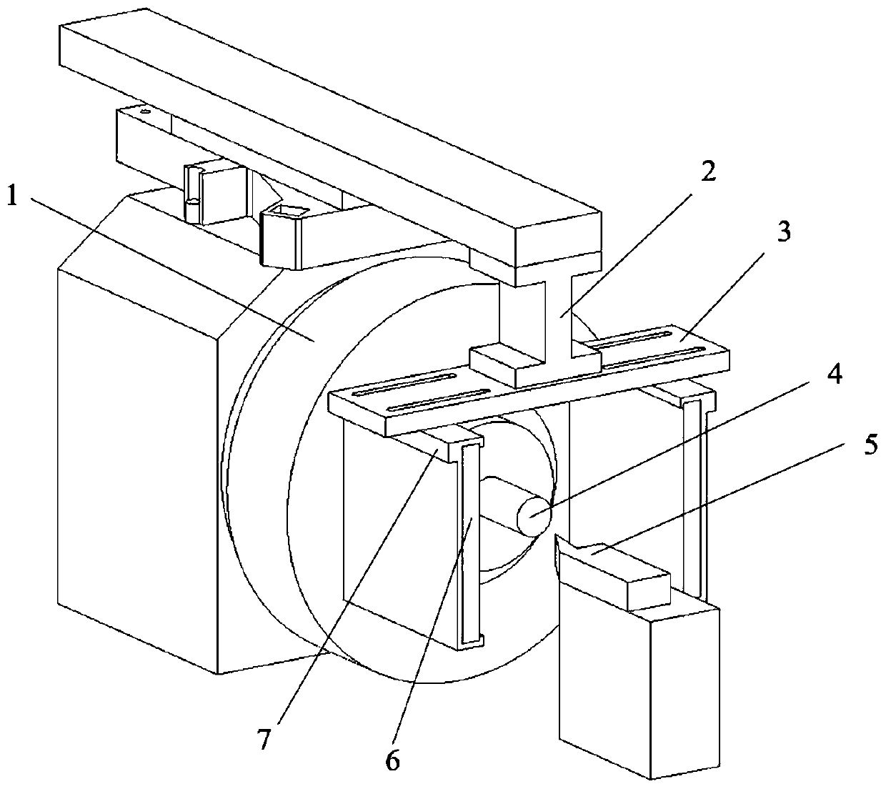
[0028] Such as figure 1 As shown, the magnetic field assisted ultra-precision machining device of the present invention includes: a machine tool body and an excitation module;

[0029] The main body of the machine tool includes: an ultra-precision machine tool spindle 1 and a tool holder 5 equipped with a diamond tool;

[0030] The excitation module includes a magnet 6 , a fixing frame 2 , an ...


PUM


Abstract

The invention belongs to the field of ultra-precision machining, and discloses a magnetic field assisted ultra-precise machining device and method. The device comprises a machine tool main body and anexcitation module, the machine tool body comprises an ultra-precision machine tool spindle and a tool rest, and the excitation module comprises a magnet, a fixing frame, an adjusting plate and magnetclamps. The adjusting plate is fixed to the machine tool body through the fixing frame. The two magnet clamps are movably arranged on the adjusting plate, two magnets with the N-S poles arranged opposite to each other are arranged on the two magnet clamps respectively, and a magnetic field of 0-0.3 T is formed between the two magnet clamps; when a spindle of the ultra-precise machine tool clampsa workpiece, the two magnet clamps are located at the two sides of the workpiece so that the machining process of the workpiece can be conducted in the magnetic field. Ultra-precise cutting is assisted by the magnetic field, so that the problems encountered in machining of difficult-to-machine materials are solved, the quality and precision of the machined surface are improved, and tool abrasion is reduced.

Description

technical field [0001] The invention belongs to the field of ultra-precision machining, and more particularly relates to a magnetic field-assisted ultra-precision machining device and method. Background technique [0002] In recent years, new high-performance materials, such as nickel-based superalloys, titanium alloys, high-strength steels, composite materials and other advanced materials, have been more and more widely used in aerospace and other fields due to their excellent performance. These materials show processing problems such as high processing hardness, large cutting force, high cutting temperature, severe tool wear, low processing efficiency, and unsatisfactory processing quality during processing, and are typical difficult-to-machine materials. Ultra-precision diamond cutting is widely used in the processing of optical-grade surface precision parts, but it is very difficult to directly perform ultra-precision machining on the above-mentioned difficult-to-machine...

Claims


Application Information

Patent Timeline
IPC IPC(8): B23Q3/154
CPCB23Q3/1543
Inventor 许剑锋肖峻峰郭枫牛牧原吴佳理王强陈肖张建国
Owner HUAZHONG UNIV OF SCI & TECH
Learn More