
Device and method for multi-optical-fiber high-speed rotating wiredrawing side face fusion beam combination

A high-speed rotation and multi-fiber technology, applied in the field of optical fiber devices, can solve the problems of low coupling efficiency and complex process of combining optical fibers, and achieve the effect of simple production, simple process operation and good stability

Pending Publication Date: 2020-04-21
成都翱翔拓创光电科技合伙企业(有限合伙)
View PDF7 Cites 2 Cited by
  • Summary
  • Abstract
  • Description
  • Claims
  • Application Information

AI Technical Summary

Problems solved by technology

[0007] In order to solve the above-mentioned technical problems that the existing side pump coupling technology is difficult to realize the low coupling efficiency and complicated process of combining optical fibers, the purpose of the invention is to provide a multi-fiber high-speed rotary drawing side melting The purpose of the fusion beam device and method is to effectively realize the integration of the pumping optical fiber and the active optical fiber, and the active optical fiber and the pumping optical fiber are fused along the side, and the heat generated by injecting the pumping light is evenly distributed, which can realize kilowatt The second purpose is to make the bundled fiber with simple process. When the fiber is drawn, it can be rotated at high speed to melt the fiber bundle along the side along the axial direction, and the coupling efficiency of the prepared fiber is higher. , more stable, can achieve high-power laser output and bidirectional pumping

Method used


Image

  • Device and method for multi-optical-fiber high-speed rotating wiredrawing side face fusion beam combination
  • Device and method for multi-optical-fiber high-speed rotating wiredrawing side face fusion beam combination
  • Device and method for multi-optical-fiber high-speed rotating wiredrawing side face fusion beam combination

Examples


Embodiment 3

[0064] This embodiment is based on Embodiment 1, which discloses a method for bundling using a multi-fiber high-speed rotating drawing side fusion bundling device. In this embodiment, the diameter of the active fiber to be prepared is 400um, and the diameter of the pump fiber is Take 250um as an example for (1+1) composite function fiber to illustrate:

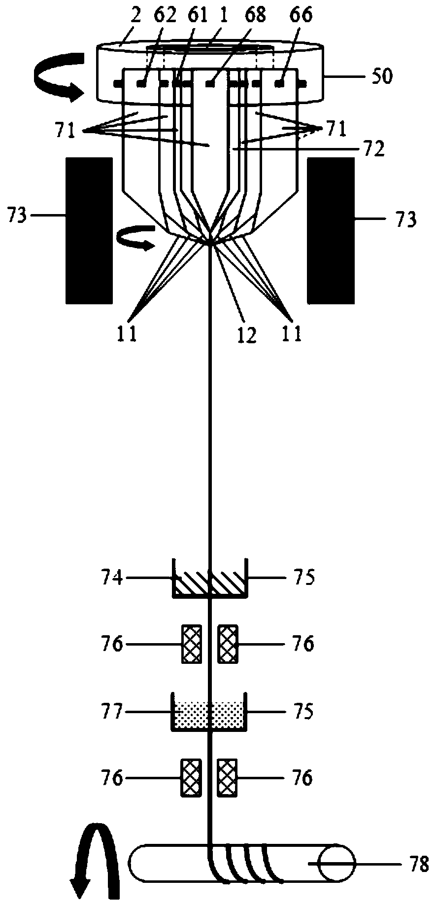
[0065] like Figure 10 As shown, the specific detailed steps of the (1+1) type composite functional fiber are as follows:

[0066] Step 1: Prepare an active optical fiber preform 12 with a diameter of about 32 mm and a pump optical fiber preform 11 with a diameter of about 20 mm, and all the preforms have the same length of 90 cm;

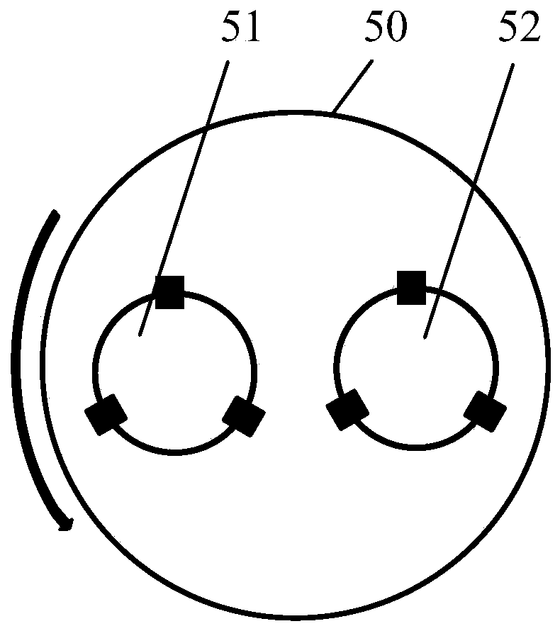
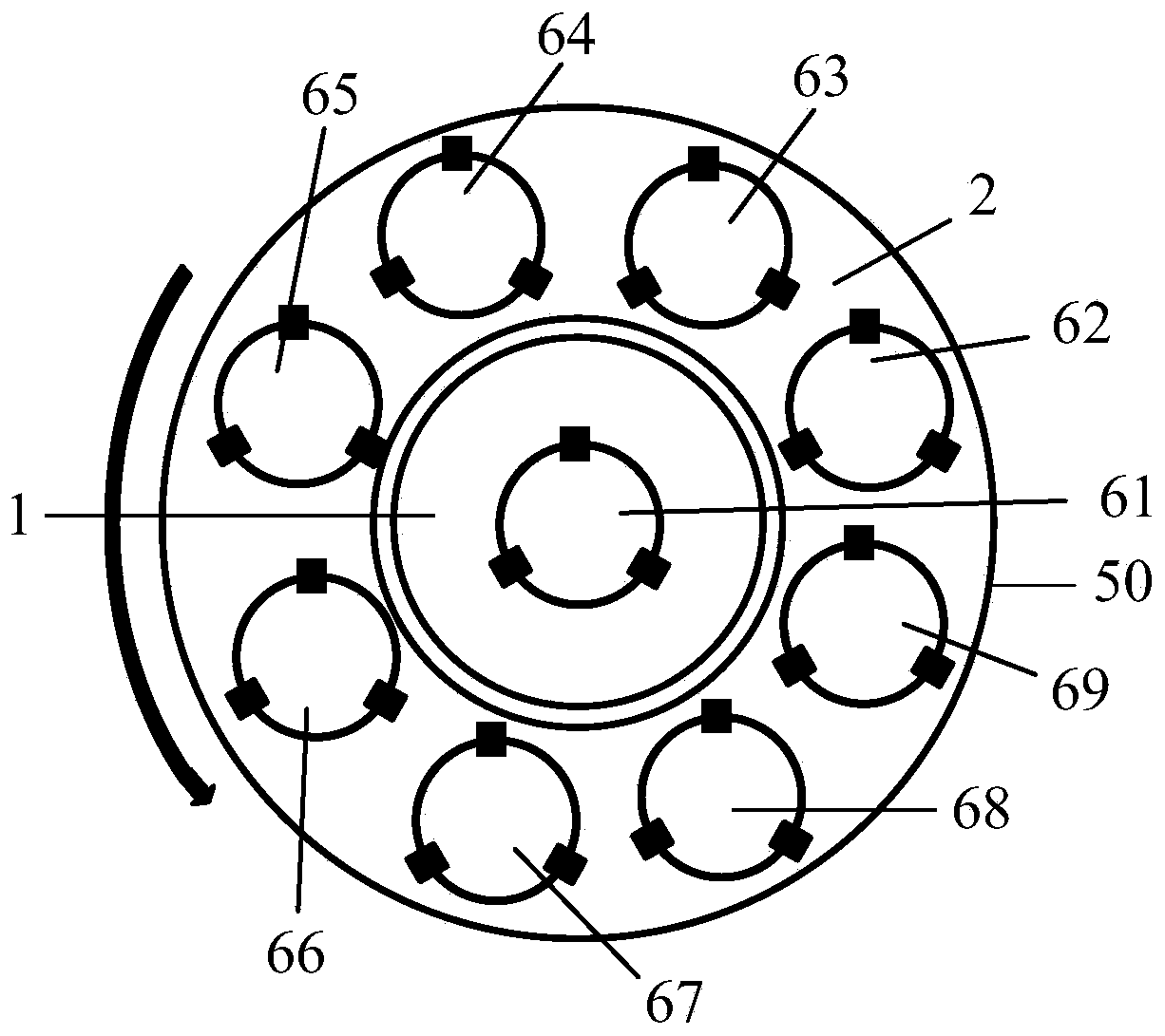
[0067] Step 2: Use such as figure 2 The shown structural schematic diagram of the chuck 50, a pump optical fiber preform 11 is clamped on the gripper 52, and the active optical fiber preform 72 is clamped on the gripper 51;

[0068] Step 3: The two optical fiber preforms fixed on the drawing to...


PUM

PropertyMeasurementUnit
lengthaaaaaaaaaa
diameteraaaaaaaaaa

Abstract

The invention discloses a device and a method for multi-optical-fiber high-speed rotating wiredrawing side face fusion beam combination. The device comprises a heating furnace, a take-up reel and a chuck, and the chuck comprises a chuck main structure and at least two grippers used for fixing an optical fiber preform; the chuck main structure is of a rotating structure, and the grippers are arranged on the chuck main structure; and the heating furnace is arranged under the chuck. The integration of a pumping optical fiber and an active optical fiber is realized, the structure is stable, and the coupling efficiency is high; several kilowatts of laser power output is achieved through double-end two-way pumping; and a composite functional optical fiber has the advantages of high coupling efficiency, simple structure, high stability and high manufacturing repeatability.

Description

technical field [0001] The invention relates to the technical field of optical fiber devices, in particular to a multi-fiber high-speed rotating wire drawing side fusion bundle device and method. Background technique [0002] Since its inception, fiber lasers have been widely used in civil industries and The military field has become one of the research hotspots in various countries and is progressing rapidly. In 2009, IPG reported that the continuous output power of single-mode fiber laser had reached 10kW. In recent years, many domestic units have also achieved power output above kilowatts. [0003] At present, high-power fiber lasers and fiber amplifiers use double-clad doped fibers, and the pumping light enters from the cladding for efficient pumping. In order to obtain high-power laser output, how to efficiently couple the pump light to the inner cladding of the active fiber is a key core technology that must be broken through in the research of fiber lasers. [0004...

Claims


Application Information

Patent Timeline
Patent Type & Authority Applications(China)
IPC IPC(8): C03B37/027C03C25/12G02B6/255
CPCC03B37/027C03C25/12G02B6/2551G02B6/2553Y02P40/57
Inventor 林傲祥王小龙倪力俞娟
Owner 成都翱翔拓创光电科技合伙企业(有限合伙)
Learn More