Gas stripping seepage draining and damming method for rotational flow pool deep layer filling

A swirling pond and air lift technology is applied in the field of stacking and reinforcement of tailings ponds and sub-dams, which can solve the problems of overall stability and imbalance of tailings ponds, slow consolidation of dry beaches of heap bodies, and long dam building, etc., and achieve drainage effects. Good, low construction cost, and the effect of shortening the construction period

Active Publication Date: 2020-04-21
付文堂 +5
View PDF5 Cites 0 Cited by
  • Summary
  • Abstract
  • Description
  • Claims
  • Application Information

AI Technical Summary

Problems solved by technology

[0002] Most of the mine tailings are transported by pipeline, and the tailings reservoir adopts upstream dam construction, and most of them use swirl bagging to build sub-dams or external materials to build sub-dams. If the infiltration line is too high and the strength is weak, the internal deformation of the dry beach will be caused by the extrusion of foreign materials used in the swirl baggi

Method used


Image

  • Gas stripping seepage draining and damming method for rotational flow pool deep layer filling
  • Gas stripping seepage draining and damming method for rotational flow pool deep layer filling
  • Gas stripping seepage draining and damming method for rotational flow pool deep layer filling

Examples


Embodiment Construction

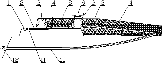
[0029] A method for building a dam with deep filling of swirling pools with gas lift and seepage drainage comprises the following steps:

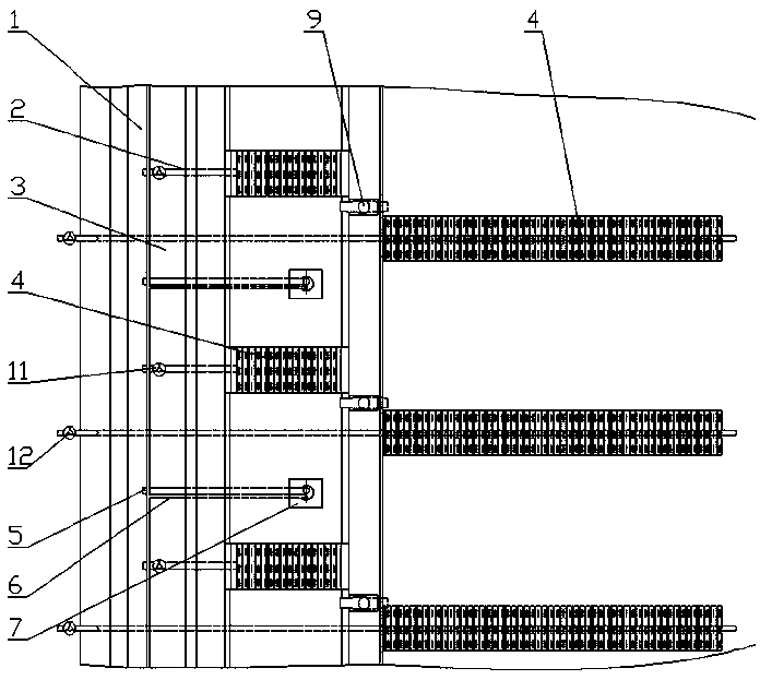
[0030] Step 1: Dig a longitudinal drainage ditch 1 on the original dam body, embed horizontal drainage pipes 2, air intake pipes 6, and air lift drainage pipes 5 according to the designed spacing. The drainage pipe 5 is laid in the middle of the two drainage pipes 2, and the horizontal drainage pipe 2 is provided with a drainage valve 11 to control the water flow switch.

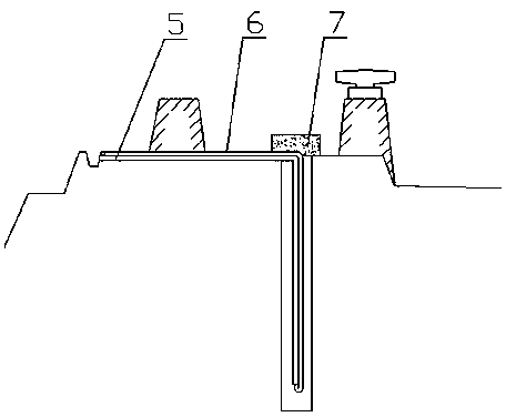
[0031] Step 2, leave a certain passage distance on the outer edge of the original dam crest and build two small dams 3 respectively on the dry beach in the dam.

[0032] Step 3, in the two small dams 3, the vertical dam body is drilled to the depth of the dam body and the seepage pipe is installed, the air intake pipe and the air lift drain pipe are put into the water seepage pipe, the bottom of the air intake pipe 6 is inserted into the air lift drain pipe 5, and the see...


PUM


Abstract

The invention discloses a gas stripping seepage draining and damming method for rotational flow pool deep layer filling. The method comprises the steps that a drainage ditch is dug in a dam body, drainage pipes, a gas inlet pipe and a gas stripping drainage pipe are buried, and an outlet of the drainage pipe provided with a drainage valve is connected into the drainage ditch; two small dams are built on a dam crest; gas stripping seepage draining devices are mounted in the two small dams and communicate with the gas inlet pipe and the gas stripping drainage pipe; slotted hole seepage drainingplates communicating with the drainage pipes are laid in a ditch pool formed between the two small dams; coarse tailings are discharged into the ditch pool; the drainage valve is opened, the seepage draining device are started, and the coarse tailings in the pool are drained and solidified; the tailings are discharged into a tailing pond to form a slope beach face; a slotted hole seepage drainingplate is laid on the slope beach face towards the interior of the pond; a water guide system with a water guide valve is mounted below the seepage draining plate; a slope beach face is formed in dry beach; and after tailing discharging is completed, the water guide valve is opened to discharge water, the tailings are solidified, and rapid damming can be continued at the dam crest through the method. According to the method, the stability and anti-sliding capacity of the dam body are improved, the strength of the dam body and the dry beach is effectively improved, and the construction cost is low.

Description

technical field [0001] The invention is applied to a tailing reservoir dam construction and reinforcement method for high water content and solid waste stockpiling and dam construction, and specifically refers to a method for dam construction by filling deep layers of swirl pools with air lift and seepage drainage. Background technique [0002] Most of the mine tailings are transported by pipeline, and the tailings reservoir adopts upstream dam construction, and most of them use swirl bagging to build sub-dams or foreign materials to build sub-dams. When constructing sub-dams, the foundation of sub-dams is located on the dry beach, and the bottom If the infiltration line is too high and the strength is weak, the internal deformation of the dry beach will be caused by the extrusion of foreign materials used in the swirl bagging dam and the reinforcement foundation, and the overall stability of the tailings pond will be out of balance, which will easily cause deformation and da...

Claims


Application Information

Patent Timeline
IPC IPC(8): E02D17/18E02B3/10E02D3/10
CPCE02B3/10E02D3/10E02D17/18Y02A10/11
Inventor 付文堂关士良张厉声王平刘宁宋海燕
Owner 付文堂
Why Eureka
Try Eureka