
Exhaust pipe insulation cover assembly and production method thereof

A technology of exhaust pipe and shield, which is applied in the field of exhaust pipe shield assembly and its preparation, and can solve the problems of exhaust pipe shield assembly appearance wrinkles, metal plate and ceramic fiber board falling off, heat shield failure, etc. , to achieve the effect of improving surface strength, increasing service life and improving heat insulation

Inactive Publication Date: 2020-04-21
浙江创格科技股份有限公司
View PDF7 Cites 1 Cited by
  • Summary
  • Abstract
  • Description
  • Claims
  • Application Information

AI Technical Summary

Problems solved by technology

The exhaust pipe cover assembly wrapped with soft refractory material has defects such as appearance wrinkles and poor thermal insulation performance
However, the existing heat shields are usually prepared by three-layer stamping and welding of ceramic fiber boards and metal plates. More metal materials are used, and the weight of the product is relatively large. Moreover, the problem of falling off between the metal plates and the ceramic fiber boards is easy to occur, resulting in the heat shield. fail

Method used


Image

  • Exhaust pipe insulation cover assembly and production method thereof
  • Exhaust pipe insulation cover assembly and production method thereof

Examples


Embodiment Construction

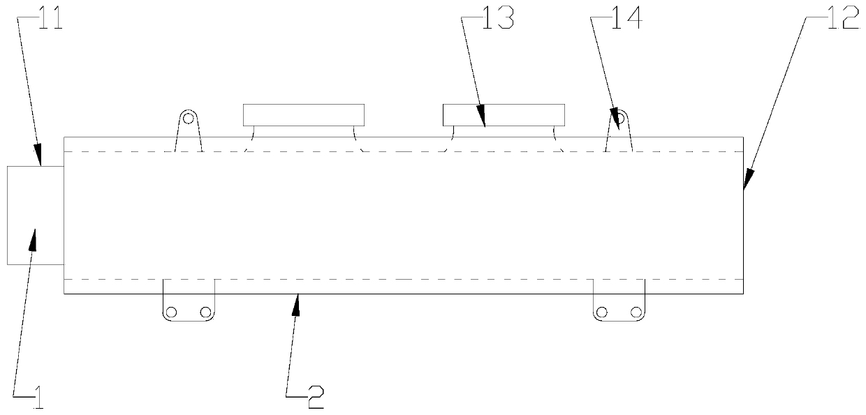
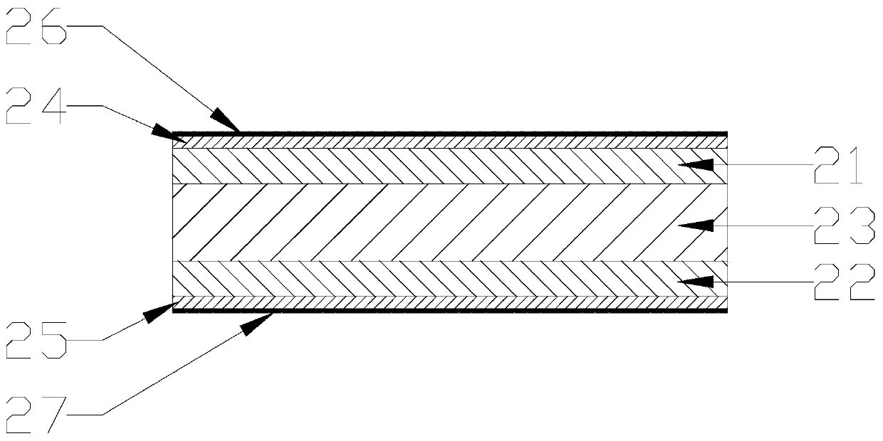
[0022] refer to figure 1 and figure 2 , an exhaust pipe shield assembly of the present invention, comprising an exhaust pipe 1 and a heat shield 2, the two ends of the exhaust pipe 1 are respectively provided with an air outlet 11 and a first air inlet 12, the exhaust pipe The side wall of the trachea 1 is provided with several second air inlets, and the air intake branch pipe 13 is fixed on the second air inlet, and several connecting plates 14 are also provided on the side wall of the exhaust pipe 1, The heat shield 2 is respectively provided with a plurality of first gaps and second gaps for the intake branch pipe 13 and the connecting plate 14 to protrude. The heat shield 2 includes a first heat insulation felt layer 21, a second insulation The thermal felt layer 22, the heat insulating fiber layer 23 between the first heat insulating felt layer 21 and the second heat insulating felt layer 22, the first hard shell layer 24 on the top surface of the first heat insulating ...


PUM

PropertyMeasurementUnit
thicknessaaaaaaaaaa
diameteraaaaaaaaaa
lengthaaaaaaaaaa

Abstract

The invention discloses an exhaust pipe insulation cover assembly and a production method of the exhaust pipe insulation cover assembly. The exhaust pipe insulation cover assembly comprises an exhaustpipe and a heat insulation cover. A plurality of second air inlets are formed in the side wall of the exhaust pipe. Air inlet branch pipes are fixed to the second air inlets. A plurality of connecting plates are arranged on the side wall of the exhaust pipe. The heat insulation cover comprises a first heat insulation felt layer, a second heat insulation felt layer, a heat insulation fiber layer located between the first insulation felt layer and the second insulation felt layer, a first hard shell layer located on the top surface of the first heat insulation felt layer, a second hard shell layer located on the bottom face of the second heat insulation felt layer, a first heat reflection layer located on the top face of the first hard shell layer and a second heat reflection layer locatedon the bottom face of the second hard shell layer. The production method of the exhaust pipe insulation cover assembly comprises the steps of a), casting, b), filling, c), hardening, d), aluminizing,e), molding, and f), mounting. The heat insulation cover is attractive in appearance and is good in fit with the exhaust pipe, the interior is fluffy, and the heat insulation performance is high.

Description

【Technical field】 [0001] The invention relates to the technical field of automobile exhaust pipeline systems, in particular to the technical field of an exhaust pipe shield assembly and a preparation method thereof. 【Background technique】 [0002] The automobile exhaust system is used to discharge the exhaust gas discharged by the engine, and at the same time reduce the noise and the pollution of the exhaust gas. When the exhaust pipe system of the automobile discharges the exhaust gas, a large amount of heat carried by the exhaust gas will heat the exhaust pipe, causing the surface temperature of the exhaust pipe to reach as high as 500-600 °C. Due to the limited space in the chassis of the car, the parts around the car exhaust pipeline system are mostly close to the car exhaust pipe, and the normal operation of the surrounding parts has strict requirements on the temperature. If the temperature is high, it is easy to cause safety hazards. accident, so the exhaust pipe nee...

Claims


Application Information

Patent Timeline
Patent Type & Authority Applications(China)
IPC IPC(8): F01N13/14F01N13/16B32B9/00B32B9/04B32B17/02B32B33/00
CPCB32B5/02B32B5/26B32B33/00B32B2255/02B32B2262/101B32B2262/105F01N13/148F01N13/16
Inventor 吴海锋方刚锋
Owner 浙江创格科技股份有限公司
Learn More