Variable vector action duration-based permanent magnet synchronous motor current control method

A technology of permanent magnet synchronous motor and current control, which is applied in vector control system, motor generator control, electronic commutation motor control, etc. It can solve problems such as large torque fluctuation, limited switching state, and increased switching loss. Achieve steady state and dynamic performance improvement, good accuracy, reduce current fluctuation and current harmonic content

Inactive Publication Date: 2020-04-21
TIANJIN UNIV
View PDF8 Cites 5 Cited by
  • Summary
  • Abstract
  • Description
  • Claims
  • Application Information

AI Technical Summary

Problems solved by technology

However, the Euler discretization method is not applicable when the sampling frequency of the motor is low, and it will bring a large error
Secondly, due to the limited switching states adopted by the finite set model predictive control strategy, only eight basic voltage vectors are used to reduce the error between the predicted value of the controlled target and the reference value [10][11] , and the action time of the voltage vector is fixed, after the end of the voltage vector action, there is still a large error between the current reference value and the predicted value, so the motor will appear high-frequency, large-scale torque fluctuations and Undesirable high frequency current harmonics
Relevant researchers try to output a combination of various switching states in a discrete control cycle to control the motor [12][13] , but the switching frequency will increase accordingly, and the switching loss will increase accordingly

Method used


Image

  • Variable vector action duration-based permanent magnet synchronous motor current control method
  • Variable vector action duration-based permanent magnet synchronous motor current control method
  • Variable vector action duration-based permanent magnet synchronous motor current control method

Examples


Embodiment 1

[0049] A method for controlling the current of a permanent magnet synchronous motor based on variable vector action duration, the method comprising the following steps:

[0050] 101: Use the zero-order hold discretization method to discretize the mathematical model of the permanent magnet motor, so that it still has better accuracy at a lower sampling frequency;

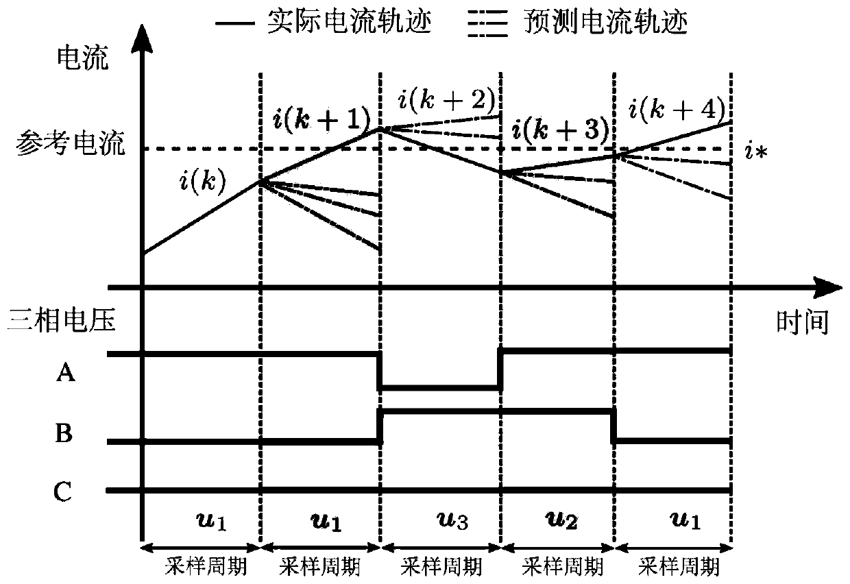
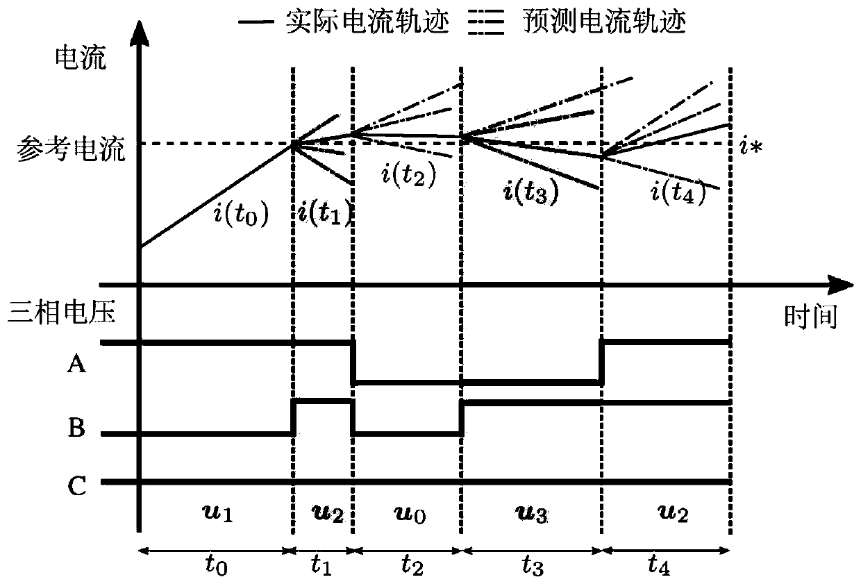
[0051] 102: Based on the precise zero-order hold discretization mathematical model of the permanent magnet synchronous motor, the dq axis current components are respectively expressed as functions of the vector action time t;

[0052] 103: Through mathematical calculation, the action time t corresponding to the minimum difference between the dq-axis current prediction value and the reference value is obtained opt , the obtained action time t opt And the corresponding candidate voltage vector is substituted into the cost function, and the voltage vector that minimizes the value of the cost function is selected as the...

Embodiment 2

[0055] The scheme in embodiment 1 is further introduced below in conjunction with specific calculation formulas and examples, see the following description for details:

[0056] In the subsequent variable representation: the vector will be expressed in bold, such as: stator current i s can be expressed as i s = i d +ji q , where i d is the d-axis current component, i q is the q-axis current component; in the stator coordinate system, the mathematical model of the surface-mounted permanent magnet motor can be expressed as:

[0057]

[0058] Among them, u s is the stator voltage vector, i s is the stator current vector, Ψ s is the stator flux vector, ψ r is the amplitude of the rotor flux linkage.

[0059] Among them, the corresponding matrix can be expressed as:

[0060]

[0061]

[0062] Among them, R s is the stator resistance, ω e is the rotor electrical angular velocity. In addition, since the present invention uses a surface-mounted permanent magnet s...

Embodiment 3

[0122] The proposed algorithm of the present invention is verified on a 2.3-kW permanent magnet synchronous motor, which is coaxially connected with a 3-kW load motor, and the load motor is controlled by Simens PM250. The proposed algorithm of the present invention is implemented by a TMS320F28379D digital signal processor (DSP). Experimental platform and detailed parameters such as Figure 6 and shown in Table 1. In order to be objective and fair, the comparison between the proposed algorithm and the traditional algorithm is carried out under the same switching frequency.

[0123] Table 1: Motor parameters

[0124]

[0125]

[0126] The first step is to compare the steady-state performance: the experimental conditions are: d-axis reference current and q-axis reference current are set to 0A and 5A respectively, the motor speed is 300r / min, and the average switching frequency is 2.7kHZ. Such as Figure 7 As shown, when the motor runs the traditional finite set model p...


PUM


Abstract

The invention discloses a variable vector action duration-based permanent magnet synchronous motor current control method. The method comprises the following steps that: the mathematic model of a permanent magnet motor is discretized through zero-order keeping discretization, and so that the mathematic model of the permanent magnet motor can still have better precision at a lower sampling frequency; based on the zero-order keeping discretization mathematical model of the permanent magnet synchronous motor, dq-axis current components are respectively expressed as functions related to a vector action time t; and a corresponding action time topt under the condition that the difference between dq-axis current prediction values and reference values is minimum is obtained, the action time topt and corresponding candidate voltage vectors are substituted into a cost function, and a voltage vector enabling the minimum value of the cost function is selected as output to control the permanent magnet synchronous motor. According to the method, the zero-order keeping discretization method is used for discretizing the mathematical model of the permanent magnet motor, so that the accurate zero-order keeping discretization mathematical model of the permanent magnet synchronous motor is obtained, so that the system still has better accuracy at the lower sampling frequency.

Description

technical field [0001] The invention relates to the field of motor systems and controls, in particular to a permanent magnet synchronous motor current control method based on variable vector action duration. Background technique [0002] The permanent magnet synchronous motor (Permanent Magnet Synchronous Motor, PMSM) uses a power electronic frequency converter to realize frequency conversion and speed regulation, and has significant advantages such as compact structure, reliable operation, low maintenance cost, and high efficiency. However, while being widely used, the permanent magnet synchronous motor system also faces many challenges under complex working conditions. Therefore, research on the control strategy of permanent magnet synchronous motor system has important theoretical value and practical significance. At present, a variety of advanced controllers have been proposed to solve the control problems of permanent magnet synchronous motors under complex working con...

Claims


Application Information

Patent Timeline
Patent Type & Authority Applications(China)
IPC IPC(8): H02P21/22H02P21/00
CPCH02P21/0021H02P21/22
Inventor 宋战锋刘擎
Owner TIANJIN UNIV
Why Eureka
Try Eureka