Burner for furnace and heating furnace

A burner and heating furnace technology, which is applied to burners, gas fuel burners, combustion methods, etc., can solve the problems of mismatching heating requirements of height-diameter ratio and heat load requirements deviating from design heat load.

Inactive Publication Date: 2020-04-24
WUHAN POLYTECHNIC UNIVERSITY +1
View PDF8 Cites 0 Cited by
  • Summary
  • Abstract
  • Description
  • Claims
  • Application Information

AI Technical Summary

Problems solved by technology

[0003] The main purpose of the present invention is to propose a furnace burner, which aims to solve the problem that the actual heat load demand of the material deviates from the design heat load during the

Method used


Image

  • Burner for furnace and heating furnace
  • Burner for furnace and heating furnace

Examples


Embodiment Construction

[0030] The following will clearly and completely describe the technical solutions in the embodiments of the present invention with reference to the accompanying drawings in the embodiments of the present invention. Obviously, the described embodiments are only part of the embodiments of the present invention, not all of them. Based on the embodiments of the present invention, all other embodiments obtained by persons of ordinary skill in the art without creative efforts fall within the protection scope of the present invention.

[0031] It should be noted that if there is a directional indication (such as up, down, left, right, front, back...) in the embodiment of the present invention, the directional indication is only used to explain the position in a certain posture (as shown in the accompanying drawing). If the specific posture changes, the directional indication will also change accordingly.

[0032] In addition, if there are descriptions involving "first", "second" and ...


PUM


Abstract

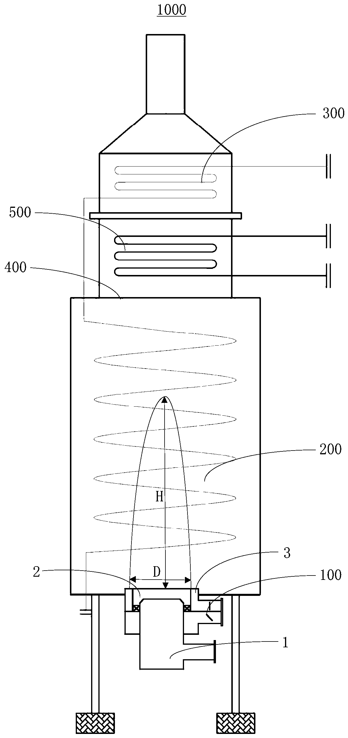
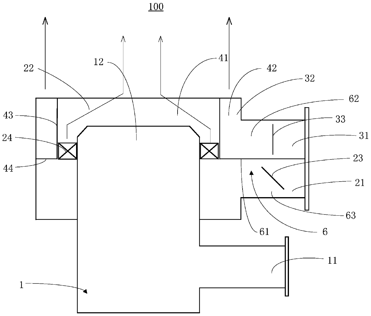
The invention discloses a burner for a furnace and a heating furnace. The burner for the furnace is in communication with a combustion chamber of the heating furnace, the burner for the furnace comprises a first channel, a first air duct and a second air duct, wherein the first outlet of the first channel is in communication with the combustion chamber and is used for providing first gas into thecombustion chamber, the first air duct outlet of the first air duct is arranged towards the first outlet and is used for providing second gas which is intersected with the spraying direction of the first gas into the combustion chamber; the second air duct outlet of the second air duct is arranged in parallel with the first outlet and is used for providing the second gas parallel to the spraying direction of the first gas into the combustion chamber, wherein one of the first gas and the second gas is fuel gas, and the other of the first gas and the second gas is combustion-supporting gas. According to the burner for the furnace, the flux of the second gas of the first air duct and the second air duct can be changed according to the condition that the actual heat load of a material deviatesfrom the designed heat load, and therefore, the flame height-to-diameter ratio of the flame sprayed by the burner for the furnace is changed so as to meet the optimal heating requirement of the material.

Description

technical field [0001] The invention relates to the technical field of combustion equipment, in particular to a furnace burner and a heating furnace. Background technique [0002] Tube heating furnace is a kind of direct heating heating equipment, generally including burner, radiation chamber, convection chamber and chimney. The burner at the bottom of the radiation chamber sprays a flame up to several meters upwards, and transfers most of the energy to the materials flowing in the furnace tube in the radiation chamber in the form of radiation heat transfer. The flue gas rises along the radiation chamber to the convection chamber, and then continues to transfer part of the heat to the materials flowing in the furnace tube in the convection chamber by convection. The temperature in the convection chamber is generally lower than that in the radiation chamber. Due to the heating requirements of different materials, before the use of the tubular heating furnace, according to th...

Claims


Application Information

Patent Timeline
IPC IPC(8): F23D14/24F23D14/46F23D14/60F23D14/70F27D99/00
CPCF23D14/24F23D14/46F23D14/60F23D14/70F27D99/0033
Inventor 徐兵李坦王明明宋光森程群鹏范国枝李云雁刘晔郑立辉
Owner WUHAN POLYTECHNIC UNIVERSITY
Why Eureka
Try Eureka