A Low Energy Pneumatic Aftershock Detection Device

A detection device and a pneumatic technology, which are applied in the field of low-energy-consumption pneumatic aftershock detection devices, can solve the problems of inability to give early warning in time, insufficient power supply, and high energy consumption, so as to increase the convenience of use, lower the manufacturing cost, and reduce the device cost. The effect of energy consumption

Active Publication Date: 2022-04-15
丰柯电子科技(上海)有限公司
View PDF15 Cites 0 Cited by
  • Summary
  • Abstract
  • Description
  • Claims
  • Application Information

AI Technical Summary

Problems solved by technology

[0004] The purpose of the present invention is to solve the problem of high energy consumption in the prior art, which needs to be charged frequently or connected to the power supply all the time. When the power supply is insufficient, it is easy to cause danger that cannot be warned in time, and a low-energy-consumption pneumatic aftershock is proposed. Detection device

Method used


Image

  • A Low Energy Pneumatic Aftershock Detection Device
  • A Low Energy Pneumatic Aftershock Detection Device
  • A Low Energy Pneumatic Aftershock Detection Device

Examples


Embodiment 1

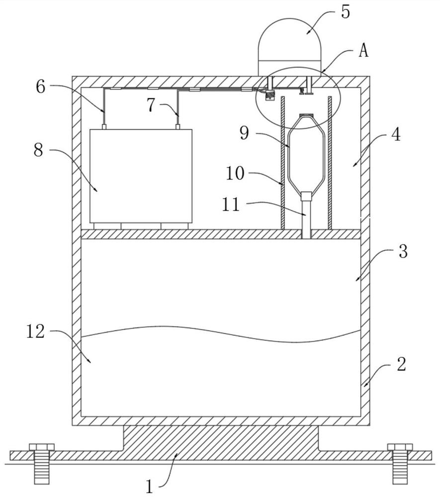
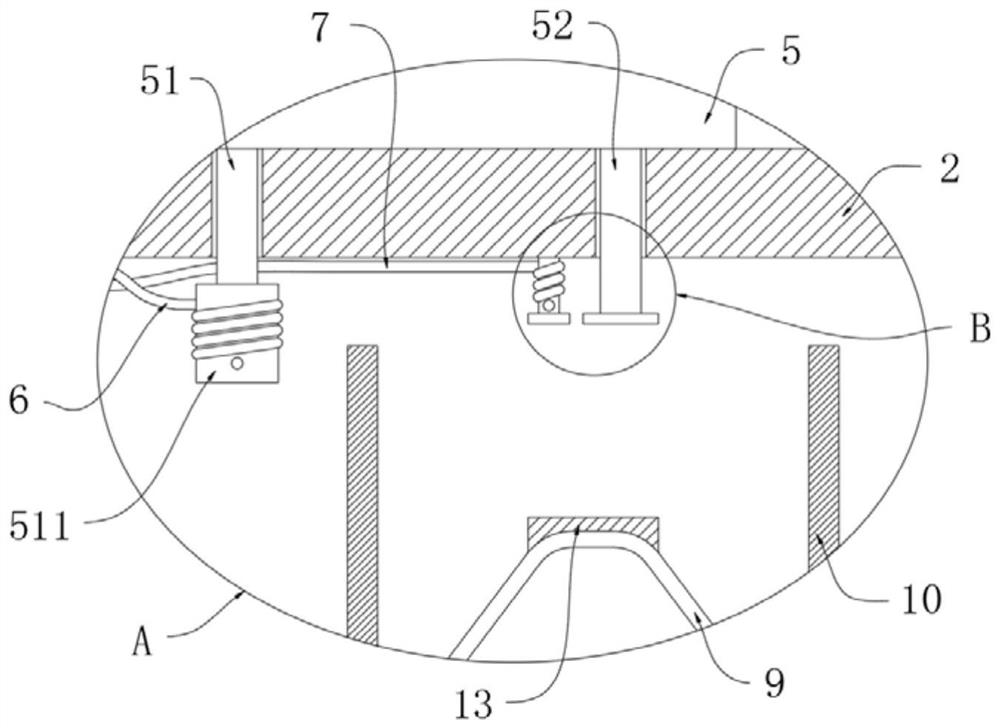
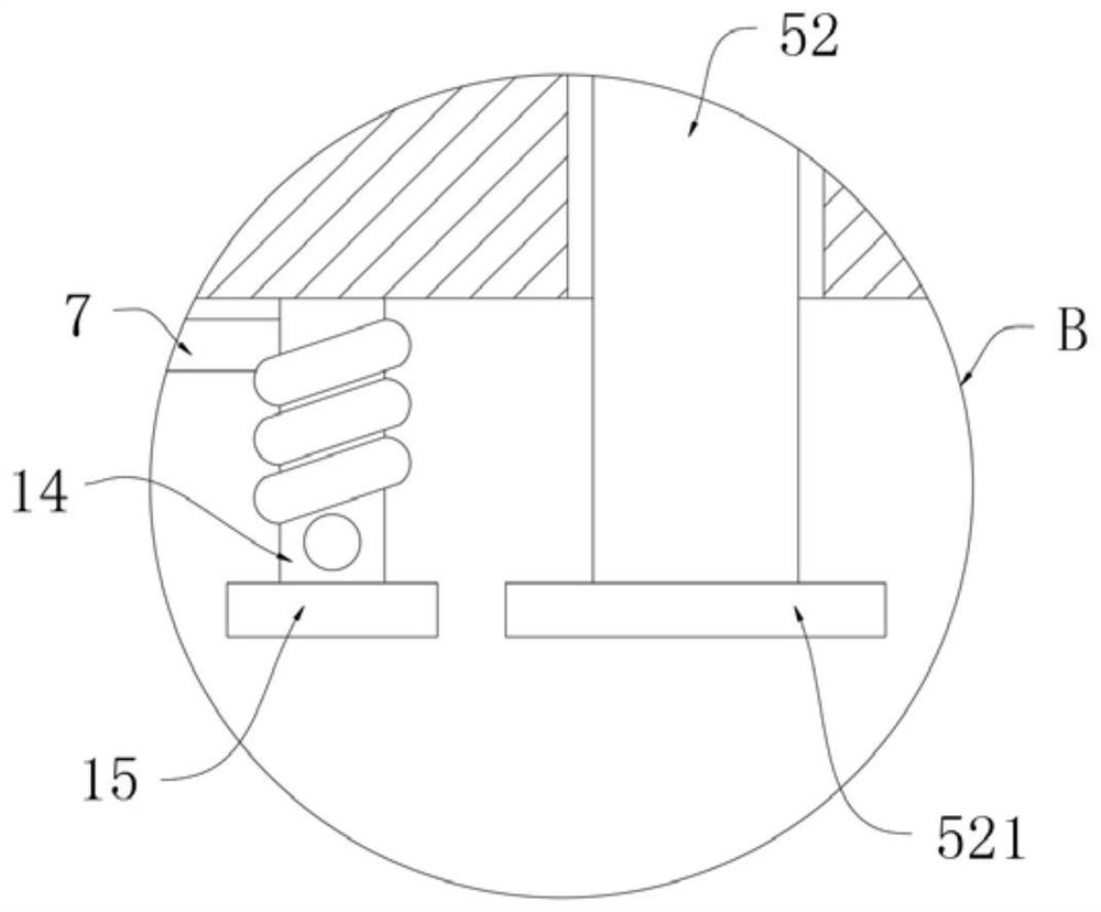
[0027] refer to Figure 1-3 , a low-energy pneumatic aftershock detection device, comprising a mounting base 1, characterized in that a box body 2 is fixedly installed on the mounting base 1, and the box body 2 is divided into an air pressure chamber 3 and a detection chamber 4, The air pressure chamber 3 is filled with a solution 12, and a trachea 11 is fixedly inserted on the inner bottom wall of the detection chamber 4, and an air bag 9 is installed on the air pipe 11, and a metal sheet 13 is fixedly installed on the upper end of the air bag 9. , the upper end of the box body 2 is equipped with a sound and light alarm 5, the sound and light alarm 5 includes a positive terminal 51 and a negative terminal 52, and the lower ends of the positive terminal 51 and the negative terminal 52 all extend to In the detection chamber 4, a wire-fixing column 511 and an electrode sheet 521 are respectively installed, and a conductive column 14 is fixedly installed on the inner top wall of ...

Embodiment 2

[0035] refer to Figure 4 , a low-energy pneumatic aftershock detection device, which is basically consistent with Embodiment 1, the difference is that:

[0036] The solution 12 is distilled water, and distilled water reacts with some metal oxides to generate gas to inflate the airbag 9;

[0037] A core tube 16 is inserted and installed in the airbag 9, and a plurality of air holes 17 are opened on the tube wall of the core tube 16, and a plurality of springs 18 and a plurality of springs 18 and a plurality of Hollow ball 19, the hollow ball 19 is filled with powder, the wall of the hollow ball 19 is provided with a plurality of micropores;

[0038] The powder is preferably sodium peroxide metal oxide powder. When the aftershock first occurs, the tiny vibration is transmitted to the box body 2, and the air bag 9 fixed by the trachea 11 in the box body 2 vibrates, causing the core tube 16 in the air bag 9 to vibrate slightly. Vibration, the small vibration of the core tube 16...


PUM


Abstract

The invention discloses a low-energy pneumatic aftershock detection device, which includes a mounting base, and is characterized in that a box body is fixedly installed on the mounting base, and the box body is divided into an air pressure chamber and a detection chamber, and the air pressure chamber A solution is injected inside, and a trachea is fixedly inserted on the inner bottom wall of the detection cavity, and an air bag is installed on the trachea. The invention keeps the circuit in an open state through the device during detection. When aftershocks occur, the circuit is turned on, which reduces the circuit loss of the device, thereby greatly reducing the energy consumption of the device. It is suitable for use in earthquake areas and can be saturated by aftershocks The vibration of the carbonic acid solution produces carbon dioxide to expand the air bag to conduct the circuit. The structure is simple and the cost is low. The staggered arrangement of hollow balls and springs in the core tube can convert tiny vibrations into high-frequency vibrations, increasing the sensitivity of detection, and sodium peroxide powder The rapid reaction with distilled water produces a large amount of oxygen to rapidly inflate the air bag, increasing the response speed of the alarm.

Description

technical field [0001] The invention relates to the field of geological disaster monitoring, in particular to a low-energy pneumatic aftershock detection device. Background technique [0002] The aggravated pollution of the earth's ecological environment has led to frequent geological disasters, including mudslides, floods, subsidence earthquakes, etc., and earthquakes occur the most frequently, and their destructive power is also the strongest and widest. Therefore, monitoring earthquakes is conducive to the rapid evacuation of people from danger. After the earthquake, there will be more aftershocks, and the aftershocks will cause secondary damage to the earthquake area, which poses a certain threat to rescue safety. [0003] Existing aftershock detection devices are usually controlled by electronic circuits, which detect ground vibrations or other seismic activity information through complex circuits and various sensors, but such earthquake detection devices consume high e...

Claims


Application Information

Patent Timeline
Patent Type & Authority Patents(China)
IPC IPC(8): G01V1/00G08B7/06G08B21/10
CPCG01V1/008G08B21/10G08B7/06
Inventor 张丽丽
Owner 丰柯电子科技(上海)有限公司
Why Eureka
Try Eureka