Large-span bridge multi-point deflection measurement method considering camera attitude change

A camera attitude and deflection measurement technology, which is applied in the testing of machines/structural components, measuring devices, elastic testing, etc., can solve problems such as the decline in displacement extraction accuracy, unsatisfactory image focus, and unsuccessful template matching, etc., to achieve visual saving. Accurate and convenient field and scale calibration, and improved work efficiency

Active Publication Date: 2020-04-28
SOUTHEAST UNIV
View PDF10 Cites 15 Cited by
  • Summary
  • Abstract
  • Description
  • Claims
  • Application Information

AI Technical Summary

Problems solved by technology

The second is that the image has problems of unsatisfactory focus and too few structural details during long-distance measurement, which reduces the accuracy of displacement extraction, and even the template matching fails, and the available effective information is insufficient.

Method used


Image

  • Large-span bridge multi-point deflection measurement method considering camera attitude change
  • Large-span bridge multi-point deflection measurement method considering camera attitude change
  • Large-span bridge multi-point deflection measurement method considering camera attitude change

Examples


Embodiment 1

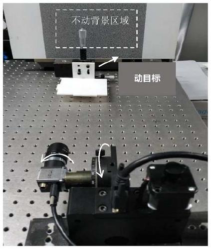
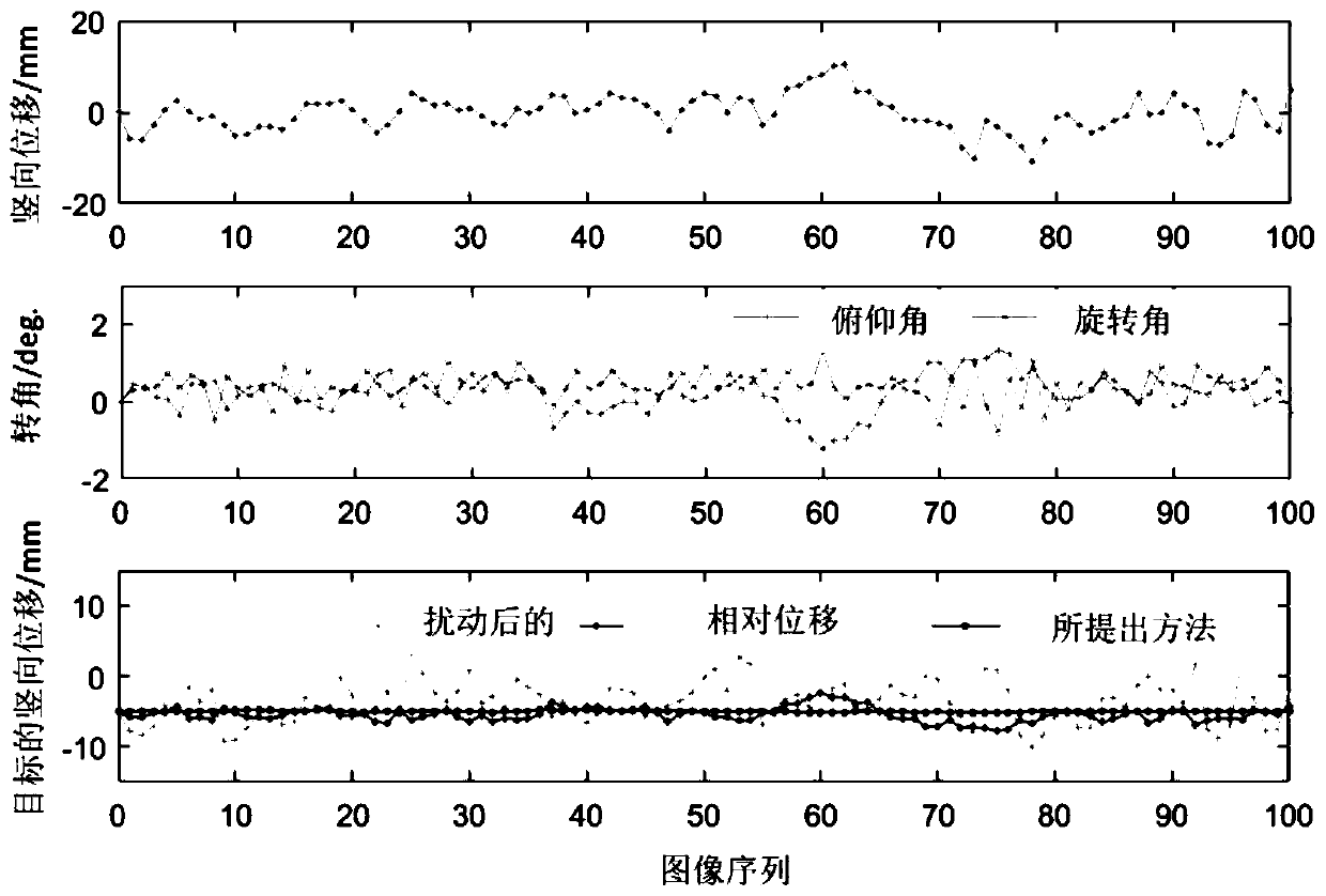
[0104] In order to verify the reliability of the deformation measurement method based on camera attitude correction proposed in this patent, a displacement platform test was carried out on the vibration isolation optical test bench. In the experimental site shown in the figure below, a UI-3370CP-M industrial camera with a resolution of 2048pixel×2048pixel and a pixel size of 5.5μm is equipped with a Kowa lens with f=25mm. This optical system is installed in a precision electronically controlled displacement The stage can provide the camera with three aspects of attitude changes: pitch, rotation around the optical axis, and in-plane rigid body displacement. The camera is clearly focused on the stable speckle area and is guaranteed to be in the same window as the target. After taking the first reference picture, the target surface is made to settle by 5mm (true value) through the translation stage, and a certain small attitude change is randomly made for the camera. Collect 100...

Embodiment 2

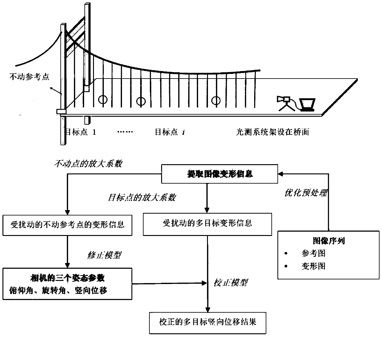
[0114] This patent uses the proposed optical measurement method to measure the deflection of multiple sections in a static load test of a long-span bridge. Stiffening beam deflection measuring points are arranged in the mid-span L / 2 (C measuring point), 3L / 8 (M1 measuring point), L / 4 (M2 measuring point), L / 8 (M3 measuring point) near the section. The test vehicle is planned to be a test truck with a total weight of 350kN. 64 trucks are loaded in four stages. like Figure 4 shown.

[0115] Step 1: Determine the layout of the optical collection system

[0116] as above Figure 5 As shown, the IDS industrial camera is equipped with f=200mm telephoto fixed-focus lens, and is erected on the inspection road across the section, with the structural surface at the bottom of the Canton Tower as a stable area. The camera is set up on the inspection road downstream of the mid-span section, with the line of sight facing the direction of the Guangdong Tower. like Image 6 As shown, ...


PUM


Abstract

The invention discloses a large-span bridge multi-point deflection measurement method considering camera attitude change. According to the invention, aiming at a picture imaging problem, Wiener filtering deblurring on an image and detail improvement based on a multi-scale image are carried out, and a template size is increased when a digital image correlation method is used to calculate vertical displacement of the image so as to control matching precision. The method has certain engineering universality, and compared with a conventional method in which a camera is erected on the shore, more view fields are saved; the camera is erected on the bridge floor, the limitation of observing structures on the outer side of the bridge through an existing optical measurement method is broken through, and a target measurement point is easier to locate; and because the camera is erected on the bridge floor, known size parameters of multiple structures can be directly utilized, and scale calibration is more convenient and accurate.

Description

technical field [0001] The invention belongs to the technical field of structural health monitoring, and in particular relates to a multi-point deflection measurement method of a long-span bridge considering camera attitude changes. Background technique [0002] Bridge maintenance, old bridge safety assessment, or new bridge acceptance mostly use displacement meters to directly measure bridge deflection. The advantages of these methods are that the equipment is simple, the deflection values ​​of each measuring point can be directly obtained, and the measurement results are stable and reliable. However, the direct measurement method needs to draw steel wires or set up shelves at each measuring point, and it cannot be measured when there is water under the bridge; due to the influence of railway or highway traffic limits, direct methods cannot be used for flyover bridges and high bridges across canyons, etc. Take measurements. This method is complicated and takes a long time ...

Claims


Application Information

Patent Timeline
Patent Type & Authority Applications(China)
IPC IPC(8): G01M5/00
CPCG01M5/0008
Inventor 张建于姗姗朱建平
Owner SOUTHEAST UNIV
Why Eureka
Try Eureka