Protection and control of wireless power systems

A technology of wireless power transmission and protection system, which is applied in the direction of protection that reacts to overvoltage, emergency protection device that automatically disconnects, emergency protection circuit device, etc., and can solve problems such as damage and dangerous operation

Pending Publication Date: 2020-05-05
WITRICITY CORP
View PDF7 Cites 0 Cited by
  • Summary
  • Abstract
  • Description
  • Claims
  • Application Information

AI Technical Summary

Problems solved by technology

The behavior of the load may be outside the control of the wireless power system and thus may cause undesired

Method used


Image

  • Protection and control of wireless power systems
  • Protection and control of wireless power systems
  • Protection and control of wireless power systems

Examples


Embodiment Construction

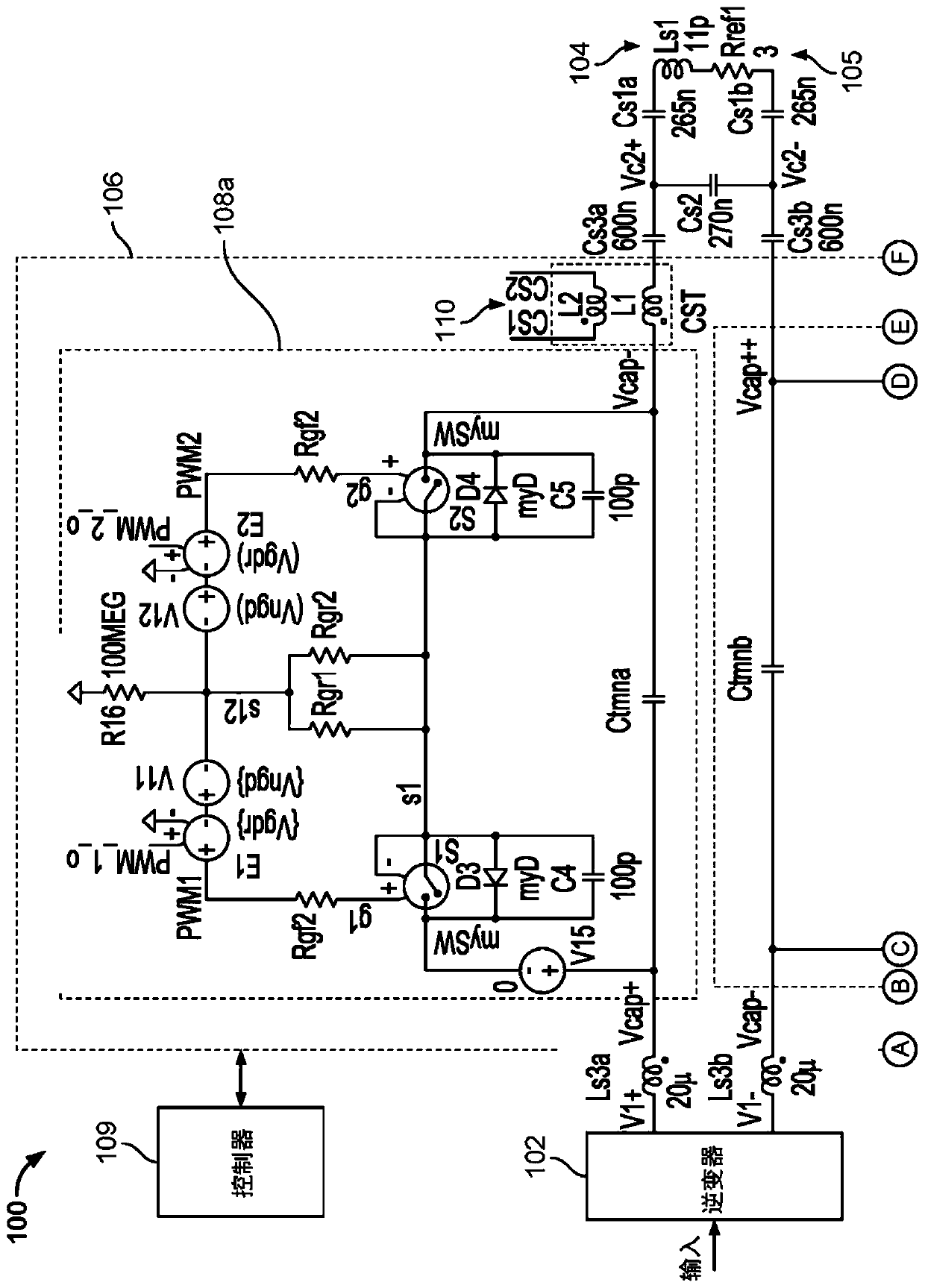
[0094] Generally, the present invention is characterized by a control and protection system for one-way and two-way wireless power transmission systems. The implementation includes sensors and protection networks to protect the wireless power transmission system from various dangerous conditions, including overvoltage, overcurrent, overtemperature, and sudden changes in power that may damage the system. The implementation includes a control system for managing the shutdown of wireless power transmission system components (eg, tunable matching network, inverter, rectifier, and inverter-rectifier) ​​in response to protection actions. The implementation includes a control system and processing for managing the reverse of power flow in a two-way wireless power transmission system.

[0095] Figure 1A It is a diagram of an equivalent model of an exemplary wireless power transmitter 100 (also referred to as a wireless power supply or grounding assembly (GA)). The wireless power transmi...


PUM


Abstract

Methods, systems, and devices for protecting a wireless power transfer system. One aspect features a sensor network for a wireless power transfer system. The sensor network includes a differential voltage sensing circuit and a current sensing circuit. The differential voltage sensing circuit is arranged within a wireless power transfer system to measure a rate of change of a voltage difference between portions of an impedance matching network and generate a first signal representing the rate of change of the voltage difference. The current sensing circuit is coupled to the differential voltagesensing circuit and configured to calculate, based on the first signal, a current through a resonator coil coupled to the wireless power transfer system.

Description

[0001] Cross references to related applications [0002] This application requires U.S. provisional patent application 62 / 526,842 filed on June 29, 2017, U.S. provisional patent application 62 / 608,052 filed on December 20, 2017, and U.S. provisional patent application 62 / 662,148 filed on April 24, 2018 , Priority of U.S. Provisional Patent Application 62 / 662,462 filed on April 25, 2018 and U.S. Provisional Patent Application 62 / 662,486 filed on April 25, 2018, the entire contents of these applications are incorporated herein by reference. Technical field [0003] The present invention generally relates to wireless power systems, and more particularly, the present invention relates to protection and sensors for wireless power systems. Background technique [0004] Wireless power systems use tunable impedance matching circuits to efficiently transmit power to coupled loads. The behavior of the load may be beyond the control of the wireless power system, and thus may cause undesirable...

Claims


Application Information

Patent Timeline
IPC IPC(8): H02J50/12H02J7/00H02H3/26
CPCH02H3/38H02H3/44H02H7/122H02H7/1227H02H7/1252H02J50/12Y02T10/7072Y02T10/70H02J7/00714H02J50/80H02J50/60H02H3/20
Inventor M·达尼洛维奇B·A·埃斯特班K·杨
Owner WITRICITY CORP
Why Eureka
Try Eureka