Automatic grinding and milling device and working method thereof

A technology of milling device and working method, which is applied in the direction of positioning device, clamping device, milling machine equipment, etc., can solve the problems of slow running speed, high cost, low efficiency, etc., to avoid milling too deep or too shallow, cost-effective, high efficiency effect

Inactive Publication Date: 2020-05-08
NANJING ENIGMA IND AUTOMATION TECH CO LTD
View PDF0 Cites 4 Cited by
  • Summary
  • Abstract
  • Description
  • Claims
  • Application Information

AI Technical Summary

Problems solved by technology

Manual grinding mainly has the following problems: 1. The life of the grinding wheel blades is low, and frequent replacement is required to seriously affect the efficiency; 2. The labor cost is high; 3. The safety is poor, and the grinding wheel blades or the aluminum chips produced by grinding have the risk of causing injury to people.
[0004] Milling machine processing also has the following problems: 1. Manual real-time online operation is required, and the running speed is slow, high cost, and low efficiency; 2. The product has high requirements, requires good product flatness consistency, and poor product tolerance

Method used


Image

  • Automatic grinding and milling device and working method thereof
  • Automatic grinding and milling device and working method thereof
  • Automatic grinding and milling device and working method thereof

Examples


Embodiment Construction

[0033] Below in conjunction with accompanying drawing and specific embodiment, further illustrate the present invention, present embodiment implements under the premise of technical solution of the present invention, should be understood that these embodiments are only for illustrating the present invention and are not intended to limit the scope of the present invention.

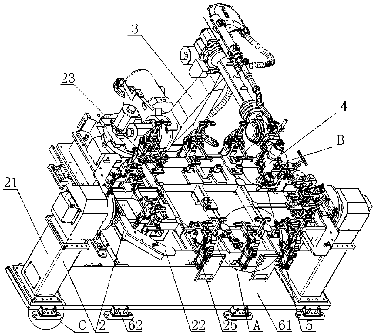
[0034] Such as figure 1 , 2 As shown in and 5, the embodiment of the present invention provides an automatic grinding and milling device, including a support 2 for placing a workpiece 1, where the workpiece 1 is a battery box support 2 provided with a workpiece positioning and clamping mechanism, and the workpiece The positioning and clamping mechanism is used to fix the workpiece 1 on the support 2 so as to grind and mill the workpiece 1 . One side of the support 2 is provided with a mechanical arm 3, and the mechanical arm 3 preferably adopts a 6-axis mechanical arm. The outer end of the mechanical arm ...


PUM


Abstract

The invention discloses an automatic grinding and milling device and working method thereof. The automatic grinding and milling device comprises a support for placing a workpieve, a workpiece positioning and clamping mechanism is arranged on the support, the workpiece positioning and clamping mechanism is used for fixing the workpiece to the support, a mechanical arm is arranged on one side of thesupport, an electric milling cutter device and a laser ranging device are arranged at the outer end of the mechanical arm, the laser ranging device is used for obtaining the actual thickness of eachdetection point position in a to-be-grinded area of the workpiece, and the mechanical arm drives the electric milling cutter device to grind and mill along the surface of the to-be-grinded area of theworkpiece according to the actual thickness of each detection point position. A robot is utilized to be matched with a milling cutter and high-precision laser to achieve full-automation operation, and the efficiency is high; the beat is fast, the efficiency is high, and the performance cost ratio is high; personnel is avoided in the whole process, and the risk of causing injury to the personnel is avoided; and the grinding height can be automatically adjusted in real time for products with inconsistent flatness, and the situation that milling is too deep or too shallow is avoided.

Description

technical field [0001] The invention relates to the field of battery tray manufacturing, in particular to an automatic grinding and milling device and a working method thereof. Background technique [0002] With the development of domestic new energy vehicles, the demand for aluminum alloy battery trays is also increasing. The technological process of the pallet mainly includes CNC machining, friction stir welding and arc welding. Among them, after the stirring welding is completed, due to the characteristics of the process itself, many burrs and flashes will be generated after the welding is completed, and because the welding deformation of the product cannot be avoided after stirring, the flatness of the product is generally poor. [0003] The main existing processing methods are manual use of angle grinders and machining by milling machines. Manual grinding mainly has the following problems: 1. The life of the grinding wheel blades is low, and frequent replacement is re...

Claims


Application Information

Patent Timeline
Patent Type & Authority Applications(China)
IPC IPC(8): B23C3/00B23Q3/08B23Q17/24B23Q17/22
CPCB23C3/00B23Q3/062B23Q3/08B23Q17/2428B23Q2703/04
Inventor 王灵通程远
Owner NANJING ENIGMA IND AUTOMATION TECH CO LTD
Why Eureka
Try Eureka