Manufacturing method of concrete relief wall

A production method and technology for concrete walls, which are applied to the preparation of building components on site, the treatment of walls and formwork, etc., which can solve the problems of easily affecting the integrity of relief patterns, poor overall molding effect of reliefs, and easy damage to relief patterns, etc. , to achieve the effect of convenient repair of local defects, good molding effect and low processing difficulty

Inactive Publication Date: 2020-05-08
金蓉
View PDF5 Cites 5 Cited by
  • Summary
  • Abstract
  • Description
  • Claims
  • Application Information

AI Technical Summary

Problems solved by technology

This method has high mold opening cost, poor economy, and complicated manufacturing process for specially customized and less used patterns. It is easy to damage the relief pattern when demoulding, and the splicing process is also likely to affect the integrity of the relief pattern. The overall molding of the relief poor effect

Method used


Image

  • Manufacturing method of concrete relief wall
  • Manufacturing method of concrete relief wall
  • Manufacturing method of concrete relief wall

Examples


Embodiment 1

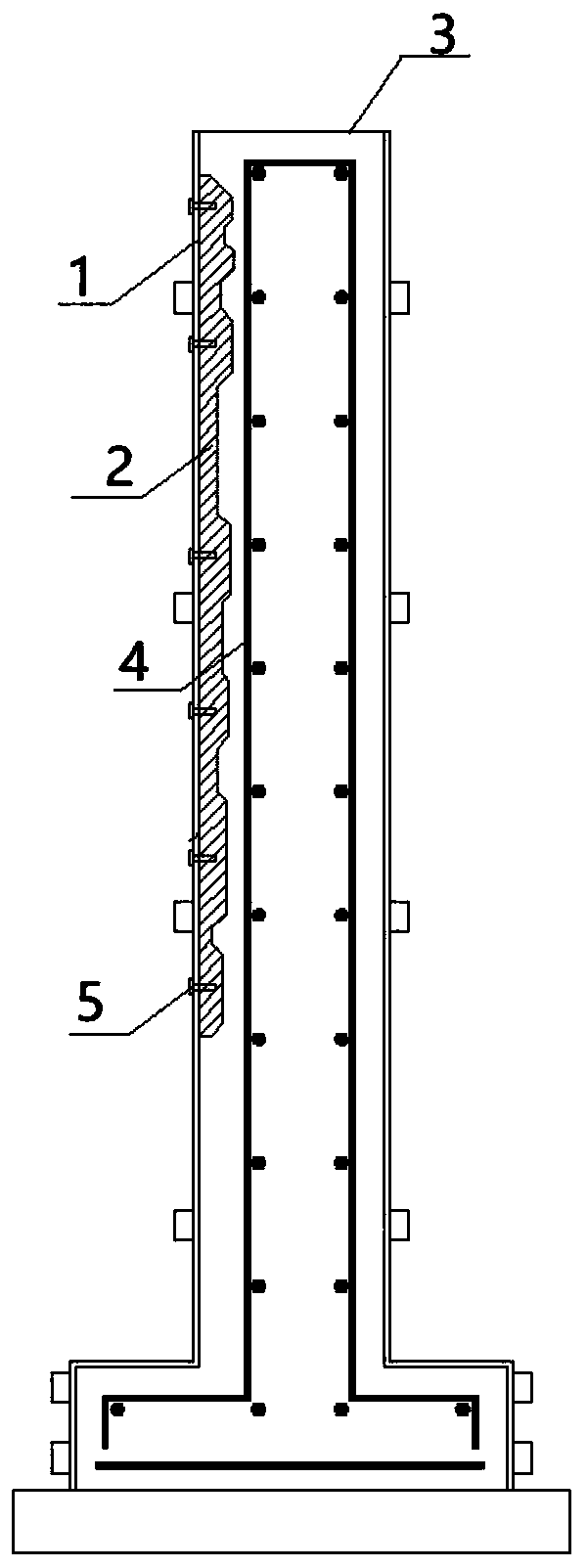
[0036] The present embodiment provides a kind of manufacture method of concrete relief wall, adopts such as figure 1 The pouring mold 3 for the concrete relief wall shown is to produce a concrete relief wall with relief patterns recessed into the wall. Include the following steps:

[0037] Step 1. According to the design plan, use the engraving machine tool or 3D printing to process the waxy female mold 2. When the waxy female mold 2 is large, it can be processed in sections to form segmented components. The material is paraffin wax, and attention should be paid to cooling down when engraving Ventilate to prevent softening of the material. The processed components are bonded with hot-melt wax, and local defects and burrs can be manually polished or repaired.

[0038] Step 2: To make the embossed formwork, first select the outer formwork 1, and the outer formwork 1 is a straight plate made of steel or aluminum, with a thinner thickness, which is convenient for demoulding in t...

Embodiment 2

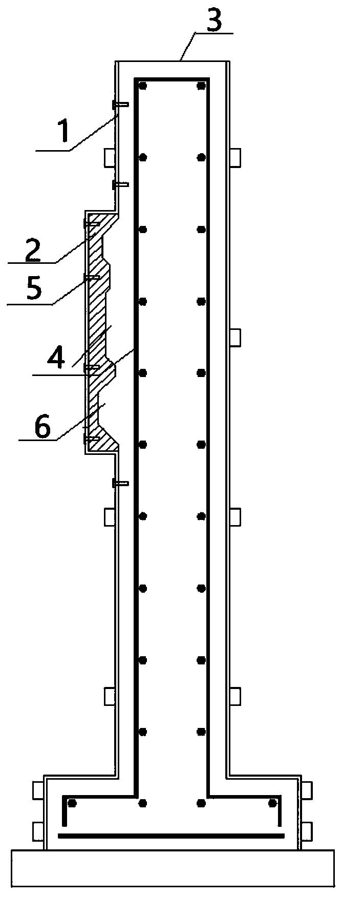
[0047] The present embodiment provides a kind of manufacture method of concrete relief wall, adopts such as figure 2The pouring mold 3 for the concrete relief wall shown in the figure produces a concrete relief wall with relief patterns protruding from the outside of the wall.

[0048] The manufacturing method of this embodiment is roughly the same as that of Embodiment 1, the difference is that in step 2, when making the embossed template, the outer template 1 protrudes outward at the embossed position to form a wax mold installation cavity 6, and the other parts are straight plates, wax molds The depth of the installation cavity 6 is equal to the depth of the waxy female mold 2, and the waxy female mold 2 is integrally filled in the wax mold installation cavity 6 to form a relief pattern protruding outside the wall after demoulding.


PUM


Abstract

The invention discloses a manufacturing method of a concrete relief wall. The manufacturing method comprises the following steps: S1, manufacturing a waxy female die according to a relief pattern; S2,manufacturing a relief die plate, coating a release agent on the inner side wall, excepting the position on which the waxy female die is mounted, of an outer side die plate, and according to the relief position, fixing the waxy female die on the inner side of a poured die plate to form the relief die plate; S3, mounting the relief die plate and other die plates in place to form a complete pouringdie; S4, pouring concrete in the pouring cavity of the pouring die; S5, separating the outer side die plate from the waxy female die, dismantling the outer side die plate, and taking out a combination of a concrete wall body and the waxy female die; and S6, adopting the heating manner to melt the waxy female die in the concrete wall body to completely melt and lose the waxy female die to obtain the concrete relief wall. According to the manufacturing method, a complicated relief and fretwork effect similar to the brick carving can be imitated on the surface of a fair-faced concrete wall, secondary decoration is not needed for the wall body, the construction speed is high, and the final effect can be shown after form removal.

Description

technical field [0001] The invention belongs to the technical field of making decorative walls, and in particular relates to a method for making a concrete relief wall. Background technique [0002] Decorative concrete wall is a kind of fair-faced concrete decoration technology that has appeared in recent years. It uses decorative concrete templates with special textures to leave patterns or bas-relief effects on the surface of the concrete, which greatly enriches the texture of fair-faced concrete walls. . However, the decorative concrete formwork can only be made into shapes with relatively simple patterns and shallow relief depths, and cannot achieve deep relief and openwork effects. [0003] The Chinese invention with the patent number of 2017102028972.5 discloses a method for making light-transmitting concrete reliefs and round sculptures. It first makes a female mold, coats the inner surface of the female mold with a release agent, and pours the adjusted concrete mort...

Claims


Application Information

Patent Timeline
Patent Type & Authority Applications(China)
IPC IPC(8): E04B2/84E04G11/08E04G19/00E04G21/00
CPCE04B2/84E04G11/08E04G19/00E04G21/00
Inventor 邹梦宬金蓉吴琛
Owner 金蓉
Why Eureka
Try Eureka