

A fiber optic gyro combination device for satellite attitude control
A technology of satellite attitude control and fiber optic gyroscope, which is applied in the direction of measuring device, Sagnac effect gyroscope, gyroscope/steering sensing equipment, etc. Good manufacturability, short heat dissipation path, and high heat conduction efficiency
- Summary
- Abstract
- Description
- Claims
- Application Information
AI Technical Summary
Problems solved by technology
Method used
Image

Examples
Embodiment 1
[0044] A fiber optic gyro combination device for satellite attitude control, comprising:
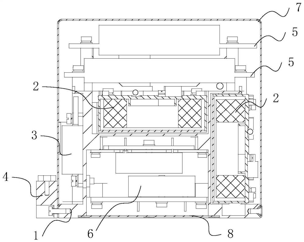
[0045] An outer cover 7 and a bottom cover 8 for packaging, the outer cover 7 and the bottom cover 8 are connected to form a cavity;
[0046] The outer cover 7 and the bottom cover 8 connected with the system body 1, the electrical connector assembly 4 connected with the system body 1, and the two gyro circuits 5 installed on the system body 1; secondary power circuit assembly 6;
[0047] The system body 1 includes a flange 10, four supporting columns 11 on the mounting flange 10, a supporting side plate 12 arranged between every two adjacent supporting columns 11, and a support side plate 12 between the four supporting columns 11. A support horizontal plate 13 arranged in the middle; four support columns 11 and four support side plates 12 form a rectangular cavity;
[0048] Two of the orthogonal optical path components 2 are respectively installed on three adjacent support columns 11;...
Embodiment 2
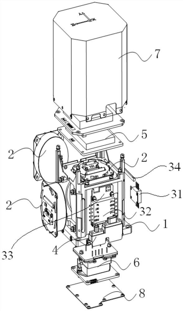
[0067] Such as figure 1 Shown is a schematic diagram of the composition of the three-axis integrated fiber optic gyro device. It can be seen from the figure that the fiber optic gyro combination device mainly includes three orthogonal optical path components 2, a light source drive component 3, an electrical connector component 5, two gyro circuits 5, and a secondary power supply Circuit assembly 6 , system body 1 , housing 7 and bottom cover 8 .
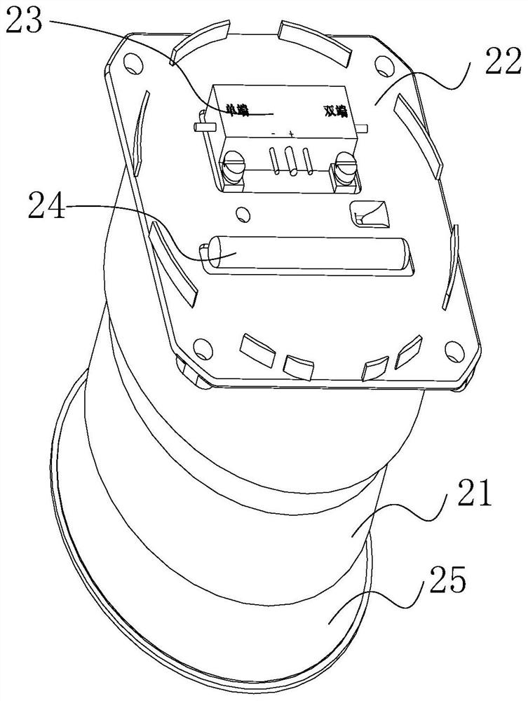
[0068] Such as image 3 It is the installation relationship diagram of optical path components, wherein the optical path components include fiber ring 21, fiber ring mounting base 22, Y waveguide 23, 2×2 coupler 24, magnetic shielding upper cover 25; the light source drive component includes SLD laser 31, drive module 32, Drive circuit 33, 3×1 coupler 34; optical fiber ring mounting base 22 is overlapped with the groove of magnetic shielding upper cover 25, forming a closed space inside, optical fiber ring 21 is installed in the in...
PUM
 Abstract
Description
Claims
Application Information