Image labeling method, device and system and host

An image tagging and host technology, applied in the field of image processing, can solve problems such as large tagging costs, negative impact on detection results, and reduced data tagging efficiency, so as to improve defect detection results, reduce tagging costs, and improve tagging efficiency

Pending Publication Date: 2020-05-08
BEIJING KUANGSHI TECH CO LTD
View PDF4 Cites 15 Cited by
  • Summary
  • Abstract
  • Description
  • Claims
  • Application Information

AI Technical Summary

Problems solved by technology

[0003] At present, the image labeling method mainly relies on manual labor, that is, it is necessary to manually label each part image to be labeled. The labeling method of a single image that relies on manual labor consumes a large labeling cost and reduces the efficiency of data labeling. ; and the quality of each image annotation data is difficult to ensure uniformity, which further has a negative impact on the detection effect

Method used


Image

  • Image labeling method, device and system and host
  • Image labeling method, device and system and host
  • Image labeling method, device and system and host

Examples


Embodiment 1

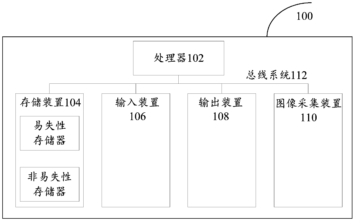
[0030] First, refer tofigure 1 An example electronic device 100 for implementing the image tagging method and device of the embodiments of the present invention will be described.

[0031] Such as figure 1 Shown is a schematic structural diagram of an electronic device. The electronic device 100 includes one or more processors 102, one or more storage devices 104, an input device 106, an output device 108, and an image acquisition device 110. These components pass through a bus system 112 and / or other forms of connection mechanisms (not shown). It should be noted that figure 1 The components and structure of the electronic device 100 shown are only exemplary, not limiting, and the electronic device may have figure 1 Some components shown may also have figure 1 Other components and structures not shown.

[0032] The processor 102 may be a central processing unit (CPU) or other forms of processing units with data processing capabilities and / or instruction execution capabilit...

Embodiment 2

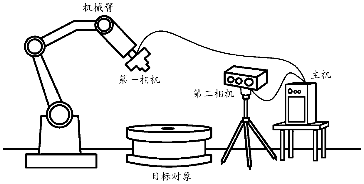
[0039] First, for ease of understanding, this embodiment provides an image tagging system, and exemplifies an actual application scenario of an image tagging method. refer to figure 2 , the image annotation system includes a host and a 2D image acquisition device and a 3D data acquisition device connected to the host; for the convenience of description, the 2D image acquisition device can also be called the first camera, and the 3D data acquisition device can be called the second camera . In practical applications, the first camera can be a monocular camera, a binocular camera or a depth camera; in order to improve the flexibility of the first camera during the image acquisition process, the first camera can be mounted on the end of the flange of the mechanical arm. In consideration of cost and manipulation complexity, the first camera may be a monocular camera. The second camera is generally a depth camera. In this embodiment, the first camera is mainly used to collect tw...

example 1

[0063] Example 1: The pose transformation relationship between the 3D model and the first camera is determined based on the pose parameters of the 3D model in the world coordinate system, the first pose transformation relationship, and the second pose transformation relationship. In practical applications, the pose parameters of the 3D model in the world coordinate system can be converted into pose parameters in the manipulator coordinate system according to the first pose transformation relationship, and then the 3D model can be transformed according to the second pose transformation relationship The pose parameters of the model in the robot arm coordinate system are converted into pose parameters in the first camera coordinate system; thereby realizing pose transformation between the 3D model and the first camera.


PUM


Abstract

The invention provides an image annotation method, device and system and a host, and relates to the technical field of image processing, and the method comprises the steps: obtaining a plurality of to-be-annotated two-dimensional images of a target object at different angles through a first camera; calculating pose parameters of the three-dimensional model of the target object corresponding to each two-dimensional image according to a pose transformation relationship between the three-dimensional model of the target object and the first camera; wherein the three-dimensional model is a model during modeling of the target object or a model constructed based on three-dimensional point cloud data of the target object; acquiring defect labeling information of the three-dimensional model; and projecting defect labeling information of the three-dimensional model to the two-dimensional images according to the pose parameters of the three-dimensional model corresponding to the two-dimensional images to obtain labeling results of the two-dimensional images. The labeling efficiency can be effectively improved, the labeling cost is reduced, and the quality of labeling results can be well unified, so that the defect detection effect of parts can be improved.

Description

technical field [0001] The present invention relates to the technical field of image processing, in particular to an image labeling method, device, system and host. Background technique [0002] At present, deep learning algorithms have been widely used in the defect detection of industrial parts, such as for detecting defects such as scratches on metal parts. In general, it is often necessary to train a neural network to detect component defects. During the training process of the neural network, the images of defective parts are marked as training data, and their quantity and quality of marking directly affect the detection effect of the neural network. [0003] At present, the image labeling method mainly relies on manual labor, that is, it is necessary to manually label each part image to be labeled. The labeling method of a single image that relies on manual labor consumes a large labeling cost and reduces the efficiency of data labeling. ; and the quality of each ima...

Claims


Application Information

Patent Timeline
Patent Type & Authority Applications(China)
IPC IPC(8): G06T7/00G06T7/70G06T7/80G06T17/00
CPCG06T7/0002G06T7/70G06T7/80G06T17/00
Inventor 王昌龙付兴银皮若言孙斯瑾李广
Owner BEIJING KUANGSHI TECH CO LTD
Why Eureka
Try Eureka