A vibration damping component of a large self-deploying satellite antenna

A satellite antenna, self-expanding technology, applied in antenna parts, antennas, folded antennas, etc., can solve the problems of nonlinear friction and vibration, large energy consumption, control frequency bandwidth, etc., to facilitate disassembly and replacement of parts, suppress frequency bandwidth, The effect of suppressing lateral vibration

Active Publication Date: 2021-10-01
BEIJING UNIV OF TECH
View PDF5 Cites 0 Cited by
  • Summary
  • Abstract
  • Description
  • Claims
  • Application Information

AI Technical Summary

Problems solved by technology

[0004] Aiming at the coupling vibration problem that is easy to occur during the deployment process of the satellite antenna and when the attitude is adjusted after deployment, the present invention designs a structural rod assembly, mainly by adding two kinds of friction dampers to the satellite support rods to absorb energy and absorb vibrations components to achieve the effect of vibration suppression, using the characteristics of large energy consumption of nonlinear friction vibration and wide frequency control, can effectively improve the effectiveness, stability and reliability of vibration control of large flexible self-deploying devices

Method used


Image

  • A vibration damping component of a large self-deploying satellite antenna
  • A vibration damping component of a large self-deploying satellite antenna
  • A vibration damping component of a large self-deploying satellite antenna

Examples


specific Embodiment approach 1

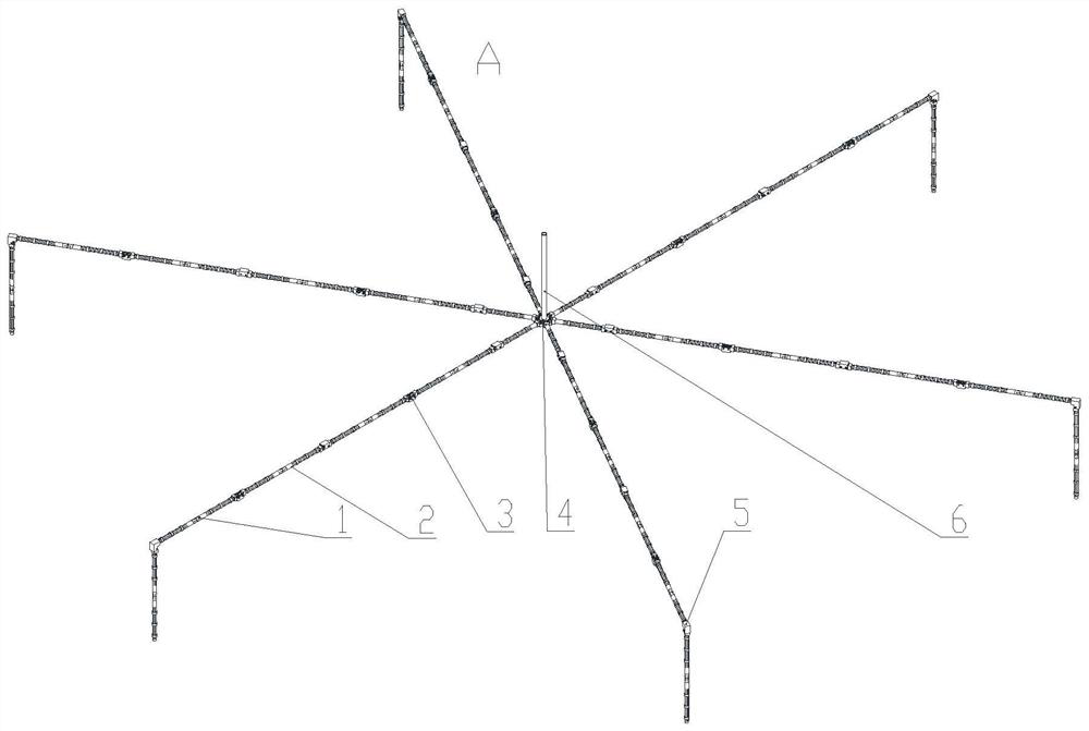
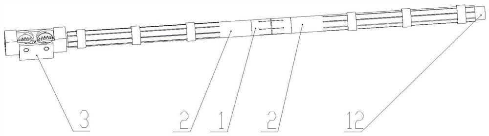
[0032] Specific implementation mode one: combine Figure 1-Figure 9 To illustrate, take the radial rib satellite antenna as an example to introduce the vibration damping member of the large self-deploying satellite antenna of the present invention. The damping member of the large-scale self-deploying satellite antenna of the present invention comprises four parts: a self-resetting axial damper 1, a multi-finger flap friction damper 2, a folding hinge assembly 3, and a support rod 12; the support rod 12 serves as The basic structural parts are respectively connected with the self-resetting axial damper 1 and the folding hinge assembly 3, and serve as the base body of the multi-finger valve pressing plate 11, and are connected with the multi-finger valve pressing plate 11 through the outer ring locking ring 10 to jointly form a multi-finger valve Friction damper 2. The radial rib assembly A is composed of six large-scale self-deploying satellite antenna vibration damping compon...

specific Embodiment approach 2

[0033] Specific implementation mode 2: Combining Figure 4 , Figure 5Note that the self-resetting axial damper 1 of this embodiment is composed of an outer sleeve 8 , metal rubber 9 , shape memory alloy wire 7 and a guide shaft 19 . The two outer sleeves 8 are butted, and the annular metal rubber 9 is used as a damping energy-dissipating element and fixed between the two outer sleeves by a guide shaft 19. The guide shaft 19 can ensure the radial stiffness and vibration direction of the damper. The shape memory alloy wire 7 has superelastic mechanical properties, and provides axial preload for the metal rubber 9 of the axial damper 1 by being wound on the two outer sleeves 8. When vibration occurs, the vibration will cause the two outer sleeves to The relative position between the sleeves 8 changes, thereby causing the stretching or compression of the metal rubber 9, and the thin metal wires in the metal rubber 9 rub against each other to consume energy and suppress vibration...

specific Embodiment approach 3

[0034] Specific implementation mode three: combination image 3 , Image 6 Explain that the multi-finger friction damper 2 of the present embodiment adopts the carbon fiber multi-finger thin-walled ring cross-section structure of the same material as the support rod 12 as the multi-finger pressure plate 11, and the root of one end of the damping structure is not split, and the hinged end of the expansion member They are firmly connected together, and the rest is a multi-finger valve structure, and is pre-pressed on the outer wall of the expansion member through the outer ring locking ring 10 . When the support bar 12 vibrates laterally, because the vibration and deformation of the multi-finger platen 11 and the structural bar 6 are different in size, relative displacement will occur between the two, and the outer locking ring 11 will be multi-finger through the pre-tightening force. The friction damper 2 exerts a frictional force, so frictional energy will be generated betwee...


PUM


Abstract

The invention discloses a vibration damping component of a large self-deploying satellite antenna, which aims to solve the surface accuracy error caused by vibration during the deployment process of the existing deployment antenna mechanism and during the attitude adjustment process after deployment. It includes multi-finger friction damper and self-resetting spring support friction damper, elastic drive hinge and satellite structure rod. The multi-finger friction damper controls the lateral vibration of the satellite deployment antenna, including a multi-finger rod, which is pressed on the structural rod through an adjustable pressure ring. The self-resetting elastic friction damper controls axial vibration, including metal rubber, guide rod, SMA pulling wire and outer sleeve. The elastically driven hinge provides deployment power through a vortex spring, and controls the deployment rate and synchronization through gears. The satellite structural rods are fixedly connected with other components to ensure the integrity of the deployed antenna. The invention is used in satellites and space probes.

Description

technical field [0001] The invention relates to the technical field of satellite flexible deployment mechanism, in particular to a vibration damping component of a large self-deploying satellite antenna, belonging to the technical field of aerospace equipment and equipment. Background technique [0002] The development of mobile communication satellites equipped with large-aperture antennas, astronomical exploration satellites, geosynchronous observation satellites, and military reconnaissance satellites is the core technology for establishing high-resolution earth observation systems and space-based earth observation and detection systems. With the development of satellite technology, large-scale flexible self-deploying antennas are gradually developing towards the two technical characteristics of large deployment size and high surface accuracy, and the design requirements are getting higher and higher. Due to the limitation of the payload of the launch vehicle and the size...

Claims


Application Information

Patent Timeline
Patent Type & Authority Patents(China)
IPC IPC(8): H01Q1/00H01Q1/28H01Q1/08H01Q1/12
CPCH01Q1/005H01Q1/08H01Q1/12H01Q1/288
Inventor 王民刘钦达赵婷婷刘佳星
Owner BEIJING UNIV OF TECH
Why Eureka
Try Eureka