Supercharge Your Innovation With Domain-Expert AI Agents!

System and method for rapid scanning test of ICR module

A fast scanning and testing system technology, applied in the direction of electromagnetic receivers, receiver monitoring, etc., can solve the problems of high backup cost, low degree of automation, expensive test equipment, etc., and achieve low requirements for testers, simple maintenance and calibration, and saving The effect of testing costs

Active Publication Date: 2020-05-08
SHENZHEN NEOPHOTONICS TECH
View PDF8 Cites 0 Cited by
  • Summary
  • Abstract
  • Description
  • Claims
  • Application Information

AI Technical Summary

Problems solved by technology

The most direct way is to use Lightwave Component Analyzer (LCA: Lightwave Component Analyzer) equipment plus some other auxiliary equipment to realize the test, but this kind of test equipment is very expensive, and the cost of a 67GHz LCA is about 500,000 US dollars, plus Other auxiliary equipment, more than 600,000 US dollars
It requires a strong technical background to use, requires engineers to calibrate or maintain the system, and it is difficult to train general employees to operate, and because the degree of automation is relatively low, human intervention is required in many places, so the test time is long
Due to the high cost of the LCA system and the high cost of backup, once a failure occurs, it will take a long time to repair or repurchase
Furthermore, the test application field of LCA is very narrow, and it can only perform tests related to radio frequency characteristics, and cannot test the optical performance of ICR and other optical devices, such as the IQ angle of ICR, responsivity, polarization extinction ratio of the chip, and the optical performance of the chip. Frequency efficiency, DC common mode rejection ratio and other optical parameters, etc., it is also necessary to use other equipment to test the optical performance of ICR
In addition, because LCA is difficult to apply to other projects, the LCA solution has great limitations for ICR mass testing, and cannot flexibly respond to changes in production capacity. Once the demand for production capacity decreases, it will become idle equipment, causing resources Great waste

Method used


Image

  • System and method for rapid scanning test of ICR module
  • System and method for rapid scanning test of ICR module
  • System and method for rapid scanning test of ICR module

Examples


Embodiment Construction

[0032] Now in conjunction with the accompanying drawings, the preferred embodiments of the present invention will be described in detail.

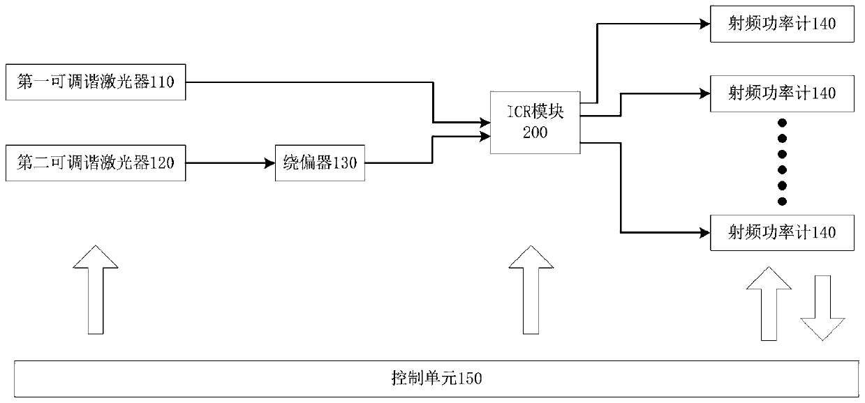
[0033] Such as figure 1 As shown, the present invention provides a preferred embodiment of a rapid scan test system for an ICR module 200 .

[0034] The fast scanning test system includes a first tunable laser 110, a second tunable laser 120, a polarizer 130, a radio frequency power meter 140 and a control unit 150, the input of the first tunable laser 110 and the tested ICR module 200 The second tunable laser 120 communicates with the input terminal of the ICR module 200 under test through the polarizer 130, and a plurality of radio frequency power meters 140 are respectively communicated with a plurality of output channels of the ICR module 200 under test, and the control unit 150 They are respectively connected to the first tunable laser 110 , the second tunable laser 120 , the ICR module 200 and the radio frequency power meter 140 . ...


PUM


Abstract

The invention relates to the field of ICR module testing, and concretely relates to a system and method for rapid scanning test of an ICR module. The rapid scanning test system comprises: a first tunable laser and a second tunable laser, wherein the output end of the second tunable laser is connected to a polarizer; a plurality of radiofrequency power meters, wherein each radiofrequency power meter is connected with one output channel of the ICR module and reads the radio frequency signal intensity output by the output channel; and a control unit for acquiring acquired data of the radiofrequency power meters and processes the acquired data to obtain a test result based on the ICR module. The system and the method for rapid scanning test of the ICR module are designed, so the ICR module canbe rapidly tested, the cost is low (the cost is 1 / 3-1 / 4 of that of an LCA test), the test result is consistent with or similar to that of the LCA test, the 3dB bandwidth difference is within 0.2 GHz,and the production test requirement is met.

Description

technical field [0001] The invention relates to the field of testing of ICR modules, in particular to a fast scanning testing system and method for ICR modules. Background technique [0002] With the rapid development of optical communication, high-definition TV, video, games, Internet of Things, etc. have entered our lives, and at the same time, people's demand for communication capacity is increasing. The traditional modulation mode amplitude modulation and frequency modulation are affected by optical fiber dispersion. It is difficult to meet the long-distance large-capacity 100Gbps, 200Gbps or even higher-capacity transmission. The coherent modulation mode has become the mainstream technology for long-distance signal transmission, and the ICR is the core device for coherent modulation reception. [0003] ICR is a device based on the principle of light coherence: two beams of linearly polarized light with the same polarization and frequencies of f1 and fn (assuming f1<f...

Claims


Application Information

Patent Timeline
IPC IPC(8): H04B10/61H04B17/29
CPCH04B10/61H04B17/29
Inventor 刘宸徐琼赵明阳
Owner SHENZHEN NEOPHOTONICS TECH
Features
  • R&D
  • Intellectual Property
  • Life Sciences
  • Materials
  • Tech Scout
  • Unparalleled Data Quality
  • Higher Quality Content
  • 60% Fewer Hallucinations
Learn More