Milling cutter for machining carbon fiber composite material

A composite material and carbon fiber technology, used in milling cutters, metal processing equipment, tools for milling machines, etc., can solve the problems of edge splitting or burrs on carbon fiber composite boards, splitting or burrs on composite boards, and avoid carbon fiber. The effect of powder accumulation and easy cutting

Inactive Publication Date: 2020-05-12
SUZHOU AHNO PRECISION CUTTING TECH CO LTD
View PDF0 Cites 2 Cited by
  • Summary
  • Abstract
  • Description
  • Claims
  • Application Information

AI Technical Summary

Problems solved by technology

[0003] At present, when the commonly used milling cutter is milling the appearance of the carbon fiber composite board, the right-handed right-cut milling cutter will generate an axial component force on the cutting edge 12 of the peripheral edge of the milling cutter due to the effect of the helix angle during the processing process, and the generated axial force will be upward. The component force will pull up the fiber material on the edge of the carbon fiber composite board, causing splits or burrs on the edge of the carbon fiber composite board, such as figure 1 shown
In the same way, the left-handed right-cut milling cutter will generate axial component force on the cutting edge 12 of the milling cutter due to the effect of the helix angle during the processing process, and it is easy to generate splits or burrs on the lower edge of the composite plate.

Method used


Image

  • Milling cutter for machining carbon fiber composite material
  • Milling cutter for machining carbon fiber composite material
  • Milling cutter for machining carbon fiber composite material

Examples


Embodiment 1

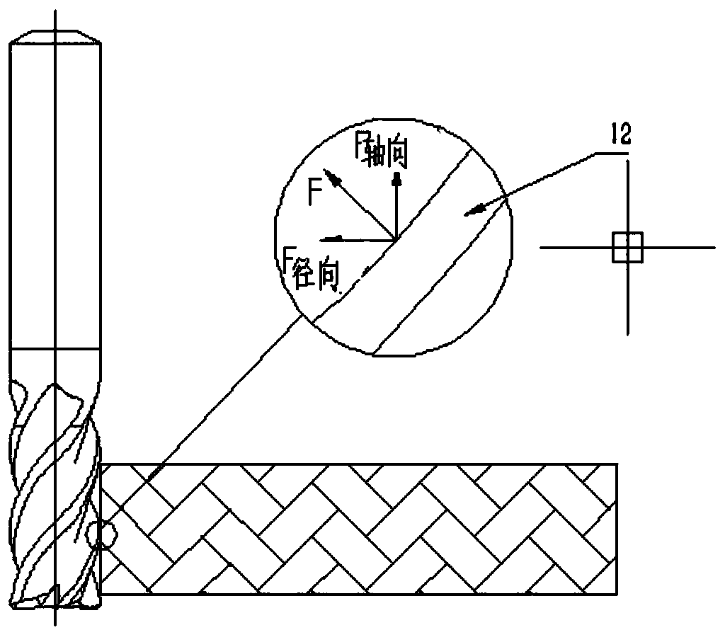
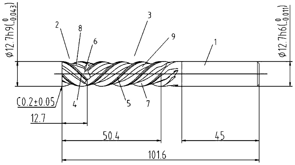
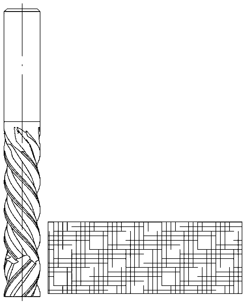
[0033] like Figure 2-8 As shown, a milling cutter for processing carbon fiber composite materials includes a cylindrical shank 1 with a diameter of 12.7mm. Shaft, the right blade part 2 includes several right-handed teeth 4 arranged in a rightward helical direction along the circumferential direction, and the left blade part 3 includes several left-handed teeth 5 arranged in a reverse helical manner with the right-handed teeth 4 along the circumferential direction, for To prevent no cutting ability between the right-handed teeth 4 and left-handed teeth 5, the right-handed teeth 4 and left-handed teeth 5 are alternately distributed and the surfaces of the two are coated with diamond super wear-resistant coating, the distance between the end of the right-handed teeth 4 and the front end of the left-handed teeth 5 The distance is denoted as L, and the value range of L is 0.6-0.8mm. The right-handed teeth 4 form right-handed flutes a6 with each other, and the left-handed teeth 5 ...


PUM

PropertyMeasurementUnit
diameteraaaaaaaaaa
lengthaaaaaaaaaa
lengthaaaaaaaaaa

Abstract

The invention discloses a milling cutter for machining a carbon fiber composite material. The milling cutter comprises a handle part, a right blade part and a left blade part are sequentially arrangedat the front end of the handle part from left to right, the right blade part comprises a plurality of right-handed teeth spirally arranged rightwards in the circumferential direction, the left bladepart comprises a plurality of left-handed teeth spirally arranged in the direction opposite to the right-handed teeth in the circumferential direction, wherein the right-handed teeth and the left-handed teeth are distributed in a staggered mode, the surfaces of the right-handed teeth and the surfaces of the left-handed teeth are coated with diamond super-wear-resistant coatings correspondingly, the distance between the tail ends of the right-handed teeth and the front ends of the left-handed teeth is 0.6-0.8 mm, right-handed chip discharge grooves a are formed among the right-handed teeth, andleft-handed chip discharge grooves b are formed among the left-handed teeth. According to the milling cutter for machining the carbon fiber composite material, fiber splitting or burrs and the like on the upper edge and the lower edge of a carbon fiber composite plate are restrained at the same time through the opposite axial force of the right blade part and the left blade part, the chip containing space is large, larger milling cutting width can be achieved, the rigidity is good, the machined powdery carbon fiber material can be smoothly discharged, and carbon fiber powder accumulation caused by unsmooth chip discharge is avoided.

Description

technical field [0001] The invention belongs to the technical fields of cutter design and cutter application, and in particular relates to a milling cutter for processing carbon fiber composite materials. Background technique [0002] With the continuous development of the aerospace industry, major aircraft structural parts manufacturers are working hard to reduce the overall weight of the aircraft and strengthen the structural strength of the aircraft. In this process, carbon fiber composite materials rely on their low density, light weight, and high strength. The characteristics stand out among many aerospace materials, and are widely used in aircraft skins and some structural parts. At present, most carbon fiber composite panels are imported, and the weaving direction of each layer of fiber is cross-laid, and the processing difficulty is slightly lower. At the same time, due to technical limitations, most domestic carbon fiber composite panels are laid in the same direct...

Claims


Application Information

Patent Timeline
Patent Type & Authority Applications(China)
IPC IPC(8): B23C5/10
CPCB23C5/10B23C2226/31B23C2230/04
Inventor 刘健余洪万苏洲
Owner SUZHOU AHNO PRECISION CUTTING TECH CO LTD
Why Eureka
Try Eureka