
Piston Link Mechanism

A piston and piston rod technology, applied in piston pumps, mechanical equipment, machines/engines, etc., can solve the problems of large size, cylinder collision, turbulent flow, etc., and achieve the effect of large bearing capacity and safe and reliable transmission

Active Publication Date: 2022-04-08
江苏万川液压机械设备有限公司
View PDF7 Cites 0 Cited by
  • Summary
  • Abstract
  • Description
  • Claims
  • Application Information

AI Technical Summary

Problems solved by technology

[0002] Hydraulic piston sludge pump sewage pump is a tool that uses strong pressure to realize mud or sewage transmission. It is an indispensable equipment for engineering production and environmental protection equipment. Hydraulic piston sludge pump sewage pumps currently on the market use hydraulic cylinders as power The cylinder drives the piston of the working cylinder, and the inlet and outlet adopt a three-way joint. Two check valves are respectively installed as the inlet one-way check and the outlet one-way check. This structure will inevitably cause the material to pass through during the feeding and discharging process The tee, some elbows and the transmission pipeline are too long, resulting in increased resistance, which affects the operating efficiency and manufacturing cost of the whole machine, and the size of the whole machine is too large to waste resources and on-site installation space; the imported and exported one-way valve is Angle-through type, that is, the inlet and outlet of the check valve are at 90 degrees, and the material is prone to turbulence during the transmission process; there is no cooling system in the cylinder of the working cylinder, and the heat generated during the operation of the equipment cannot be conducted and dissipated in time, resulting in the aging of the piston seal of the working cylinder Failure; the hydraulic cylinder is used as a power cylinder, because the installation position of the reversing device is fixed when the hydraulic cylinder is reversing, the motion inertia and the hysteresis of the reversing valve are extremely easy to cause the piston and the two ends of the cover to collide and cause the cylinder to hit the cylinder

Method used


Image

  • Piston Link Mechanism
  • Piston Link Mechanism
  • Piston Link Mechanism

Examples


Embodiment Construction

[0019] In order to deepen the understanding of the present invention, a detailed description will be given below in conjunction with the accompanying drawings and specific embodiments. The following description serves to disclose the present invention to enable those skilled in the art to carry out the present invention. The preferred embodiments in the following description are only used as examples to explain the present invention, and are not intended to limit the present invention. Those skilled in the art can think of other obvious modifications. The basic principles of the present invention defined in the following description can be applied to other embodiments, variations, improvements, equivalents and other technical solutions without departing from the spirit and scope of the present invention. Based on the understanding of the principles of the present invention, those skilled in the art can obtain other drawings and other embodiments without creative efforts, which...


PUM


Abstract

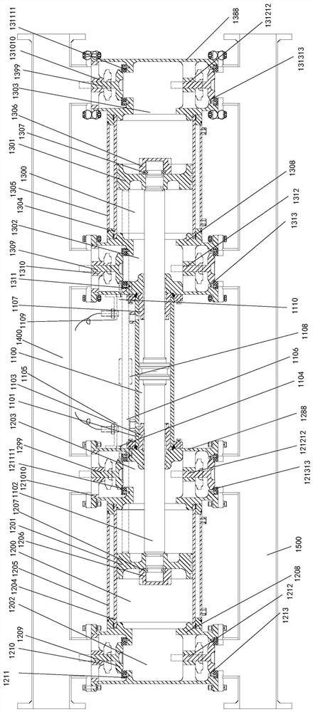
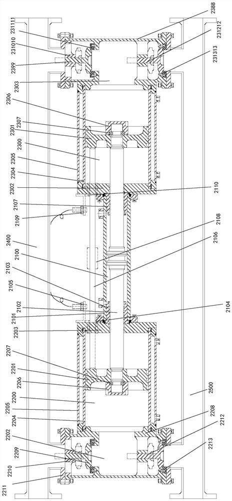
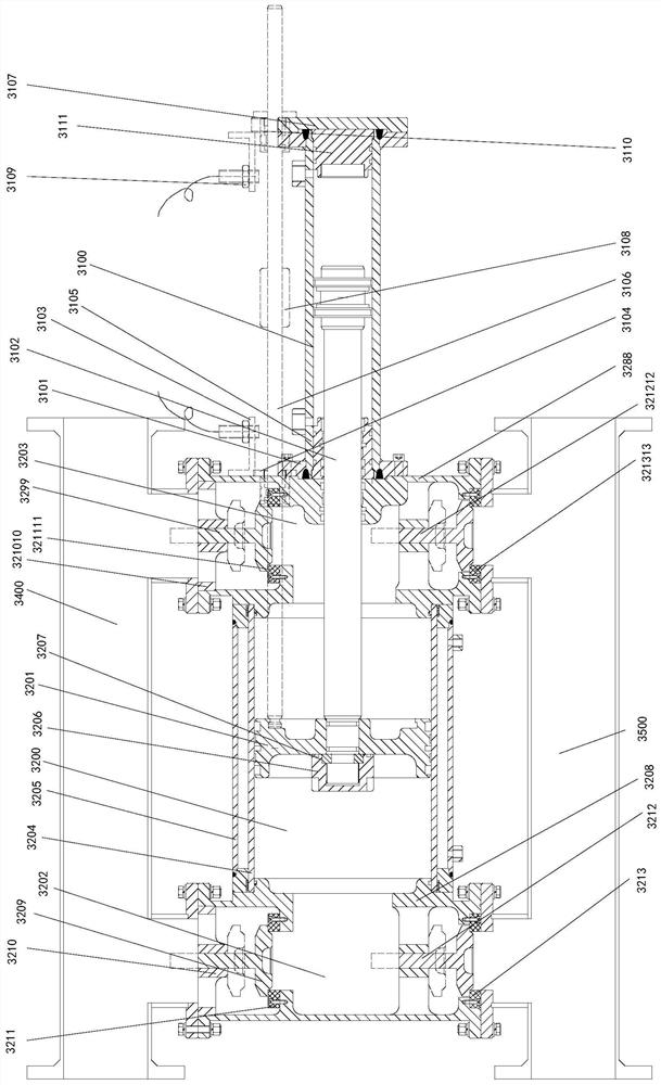
The invention provides a piston linkage mechanism, which comprises a sludge cylinder piston, a double-acting hydraulic oil cylinder piston rod, a sludge cylinder key and a sludge cylinder key self-locking nut, the sludge cylinder piston and the double The piston rod of the hydraulic oil cylinder is fixed axially and radially by the sludge cylinder key, and the sludge cylinder key is axially locked and sealed by the self-sealing nut.

Description

technical field [0001] The invention relates to the field of link mechanisms, in particular to a piston link mechanism applied to a sludge pump. Background technique [0002] Hydraulic piston sludge pump sewage pump is a tool that uses strong pressure to realize mud or sewage transmission. It is an indispensable equipment for engineering production and environmental protection equipment. Hydraulic piston sludge pump sewage pumps currently on the market use hydraulic cylinders as power The cylinder drives the piston movement of the working cylinder, and the inlet and outlet adopt a three-way joint. Two check valves are respectively installed as the inlet one-way check and the outlet one-way check. This structure will inevitably cause the material to pass through during the feeding and discharging process The tee, some elbows and the transmission pipeline are too long, resulting in increased resistance, which affects the operating efficiency and manufacturing cost of the whole...

Claims


Application Information

Patent Timeline
Patent Type & Authority Patents(China)
IPC IPC(8): F15B15/14F15B15/20F15B15/26F15B13/02F15B19/00F04B9/105
CPCF15B15/1404F15B15/1423F15B15/1433F15B15/1452F15B15/1471F15B15/20F15B15/26F15B13/02F15B19/005F04B9/105F15B2211/855F15B2211/875
Inventor 钱明慧钱言钱小刚
Owner 江苏万川液压机械设备有限公司
Learn More