A Near-Mid-Infrared Broadband Light Source Based on Multi-layer Special-shaped Array Hole Structure

A technology of broadband light source and array hole, which is applied in the direction of devices controlling laser output parameters, etc., can solve the problems of immature technology, low thermal luminescence efficiency, and high price, and achieve excellent luminous efficiency, controllable spectral composition, and low cost Effect

Active Publication Date: 2021-03-02
HUAZHONG UNIV OF SCI & TECH
View PDF6 Cites 0 Cited by
  • Summary
  • Abstract
  • Description
  • Claims
  • Application Information

AI Technical Summary

Problems solved by technology

The 2-4μm band covers the molecular fingerprints of many important molecular characteristic lines, so this band has important applications in chemistry, physics, medical application research, molecular biology, safety detection, and molecular trace detection. The mid-infrared light source represented by the halogen tungsten lamp has defects such as low thermal luminous efficiency, high temperature, and inconvenient movement.
[0004] The supercontinuum light source is moving from the laboratory to the application stage, but its technology is not mature enough, and the patent rights are in the hands of a few foreign companies, and the price is expensive

Method used


Image

  • A Near-Mid-Infrared Broadband Light Source Based on Multi-layer Special-shaped Array Hole Structure
  • A Near-Mid-Infrared Broadband Light Source Based on Multi-layer Special-shaped Array Hole Structure
  • A Near-Mid-Infrared Broadband Light Source Based on Multi-layer Special-shaped Array Hole Structure

Examples


Embodiment 1

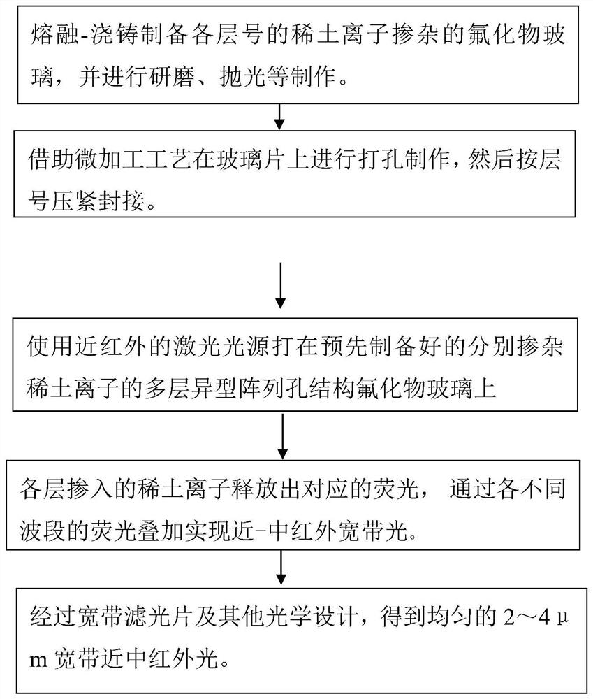
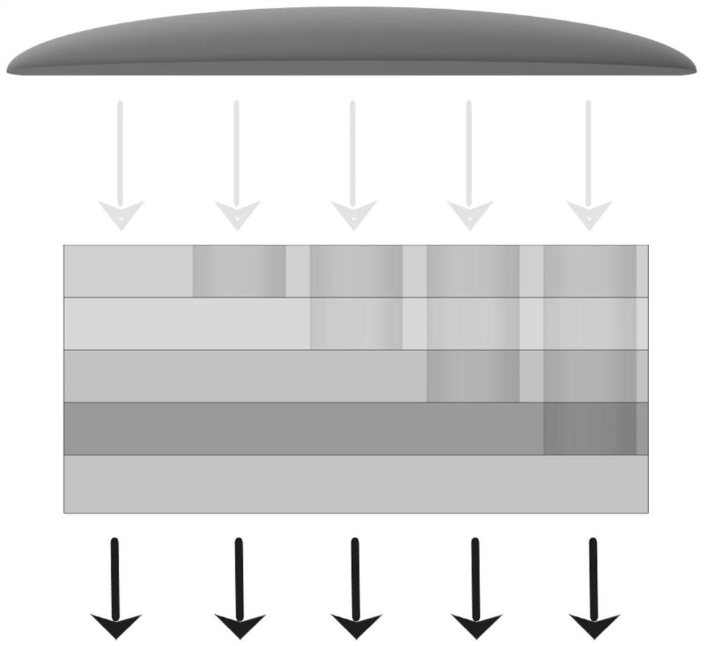
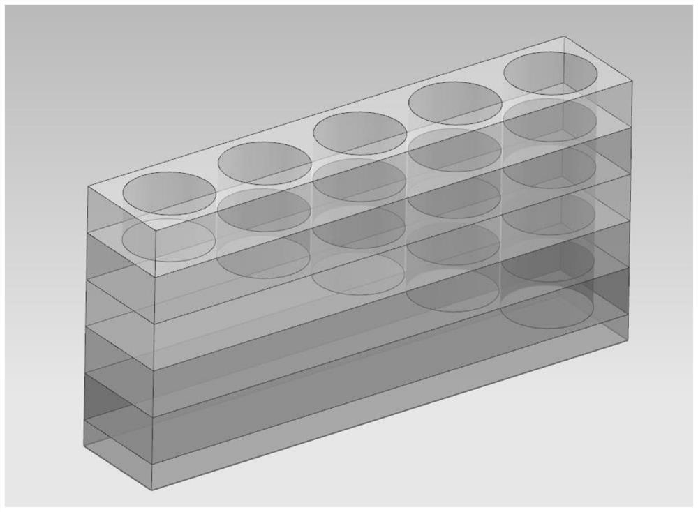
[0035] The molar percentage of No. 1 glass raw material is 48% ZrF respectively 4 , 24% BaF 2 , 8% NaF, 12% ZnF 2 , 6% A1F 3 and 2% PrF 3 ; The molar percentages of No. 2 glass raw materials are 48% ZrF respectively 4 , 24% BaF 2 , 8% NaF, 12% ZnF 2 , 6% A1F 3 and 2% TbF 3 ; The molar percentages of No. 3 glass raw materials are 48% ZrF respectively 4 , 24% BaF 2 , 8% NaF, 10% ZnF 2 , 6% A1F 3 , 1%HoF 3 and 3% TmF 3 ; The molar percentages of No. 4 glass raw materials are 48% ZrF respectively 4 , 24% BaF 2 , 8% NaF, 12% ZnF 2 , 6% A1F 3 and 2% DyF 3 ; The molar percentages of No. 5 glass raw materials are 48% ZrF respectively 4 , 24% BaF 2 , 8% NaF, 12% ZnF 2 , 6% A1F 3 and 2% TmF 3 , where No. 1 - No. 5 refers to the order from top to bottom, from light-in to light-out direction.

[0036] According to the above molar percentages, glass with a thickness of about 1mm is produced in each layer. The firing method of the glass is a conventional technical mea...

Embodiment 2

[0038] The mole percentage of No. 1 glass raw material is 35% AlF respectively 3 , 17%CaF 2 , 16%YF, 10%BaF 2 , 9%SrF 2 , 10% MgF 2 and 3% Pr 2 o 3 ; The molar percentages of No. 2 glass raw materials are 35% AlF 3 , 17%CaF 2 , 16%YF, 10%BaF 2 , 10% SrF 2 , 10% MgF 2 and 2% Tb 2 o 3 ; The molar percentages of No. 3 glass raw materials are 35% AlF 3 , 17%CaF 2 , 15% YF, 10% BaF 2 , 9%SrF 2 , 10% MgF 2 , 2% Ho 2 o 3 and 2% Tm 2 o 3 ; The molar percentages of No. 4 glass raw materials are 35% AlF 3 , 17%CaF 2 , 16%YF, 10%BaF 2 , 10% SrF 2 , 10% MgF 2 and 2% Dy2 o 3 ; The molar percentages of No. 5 glass raw materials are 35% AlF 3 , 17%CaF 2 , 16%YF, 10%BaF 2 , 10% SrF 2 , 10% MgF 2 and 2% Tm 2 o 3 .

[0039] A glass sheet with a thickness of each layer of about 1 mm is produced. The firing method of fluoride glass is a conventional technical means in the field, and is not the main point of the invention, so it will not be repeated here. After ea...


PUM

PropertyMeasurementUnit
thicknessaaaaaaaaaa
thicknessaaaaaaaaaa
fluorescence quantum yieldaaaaaaaaaa

Abstract

The invention discloses a near-mid-infrared broadband light source based on a multilayer special-shaped array hole structure. The invention uses a near-infrared laser to excite the fluorescence of glass with a multilayer special-shaped array hole structure to generate continuous infrared light. Fluoride glass has good near-infrared Mid-infrared transmittance, the rare earth ions doped in each fluoride glass layer release the fluorescence of the corresponding band under laser excitation, through the fluorescence superposition of each band under the special-shaped hole structure to achieve 2-4μm near-mid-infrared broadband light The output; the invention can flexibly adjust the doping concentration of rare earth ions on the corresponding layer according to the needs of broadband light, supplemented by glass thickness and hole array structure design, and has the advantages of small size, low power consumption, easy integration and low cost .

Description

technical field [0001] The invention belongs to the field of optical functional glass, and in particular relates to a near-middle infrared broadband light source based on a multi-layer heterogeneous array hole structure. Background technique [0002] With the development of photoelectric technology, the photoelectric detection industry is becoming more and more mature. The 2-4μm band covers the molecular fingerprints of many important molecular characteristic lines, so this band has important applications in chemistry, physics, medical application research, molecular biology, safety detection, and molecular trace detection. The mid-infrared light source represented by the halogen tungsten lamp has defects such as low thermal luminescence efficiency, high temperature, and inconvenient movement. [0003] Infrared LEDs, infrared lasers and other infrared light sources have narrow spectrums, and there are few light sources covering 2-4 μm, while the near-mid infrared band is a ...

Claims


Application Information

Patent Timeline
Patent Type & Authority Patents(China)
IPC IPC(8): H01S5/06
CPCH01S5/06
Inventor 王双保陶恺宇
Owner HUAZHONG UNIV OF SCI & TECH
Why Eureka
Try Eureka