Power cabinet
A power cabinet and power unit technology, which is applied in the direction of output power conversion device, AC power input conversion to DC power output, cooling/ventilation/heating transformation, etc., can solve high cost, inconvenient maintenance, inconvenient power cabinet modularization and Platform-based development and other issues to achieve the effect of ensuring sealing performance, reducing heat generation, and compact structure
- Summary
- Abstract
- Description
- Claims
- Application Information
AI Technical Summary
Problems solved by technology
Method used
Image

Examples
Embodiment 1
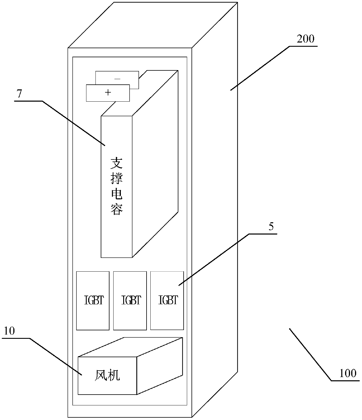
[0049] as attached figure 1 , and attached Figures 4 to 8 As shown, an embodiment of a power cabinet specifically includes: a cabinet body 200 and a power unit 2 (using a TPM01 type power unit) disposed in the cabinet body 200 , a pulse control module 3 , a load board 9 and a cooling fan 10 . The power unit 2, the pulse control module 3 and the cooling fan 10 all adopt a drawer structure, which are pushed into and fixed on the frame 1 of the cabinet body 200, and fastened from the outside of the frame 1, so as to facilitate the disassembly and assembly of each module in the later stage. maintain. The bearing plate 9 is arranged on the skeleton 1 , the power unit 2 is arranged above the bearing plate 9 , and the fan 10 is arranged at a position corresponding to the power unit 2 under the bearing plate 9 . Two pairs of lower push-in guide rails 11 and upper push-in guide rails 12 are arranged parallel to each other and opposite to each other at the bottom of the carrier plate...
Embodiment 2
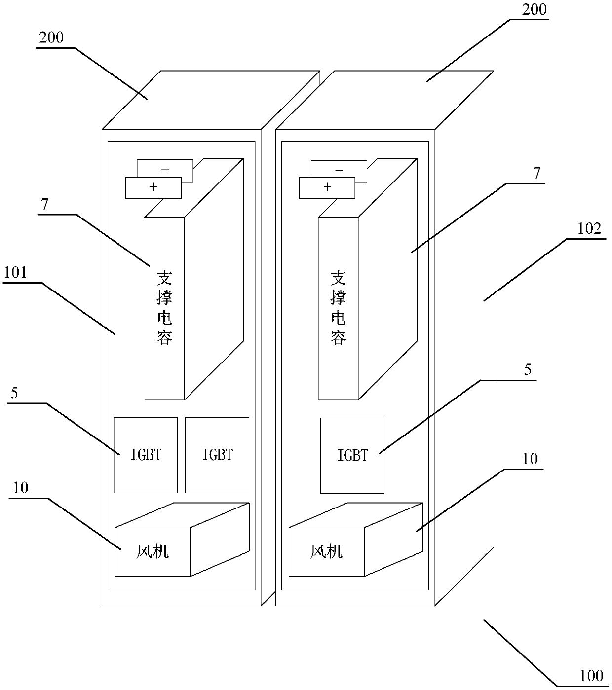
[0059] as attached figure 2 , and attached Figure 12 As shown, another embodiment of the power cabinet specifically includes: a first unit cabinet 101 and a second unit cabinet 102, the first unit cabinet 101 and the second unit cabinet 102 both include a cabinet body 200 and are arranged in the cabinet body 200 Power unit 2 (using TPM02 type power unit), pulse control module 3, load board 9 and cooling fan 10. The power unit 2 , the pulse control module 3 and the cooling fan 10 all adopt a drawer structure, which are pushed into and fixed on the frame 1 of the cabinet body 200 , and fastened from the outside of the frame 1 . The bearing plate 9 is arranged on the skeleton 1 , the power unit 2 is arranged above the bearing plate 9 , and the fan 10 is arranged at a position corresponding to the power unit 2 under the bearing plate 9 . Two pairs of lower push-in guide rails 11 and upper push-in guide rails 12 are arranged parallel to each other and opposite to each other at ...
Embodiment 3
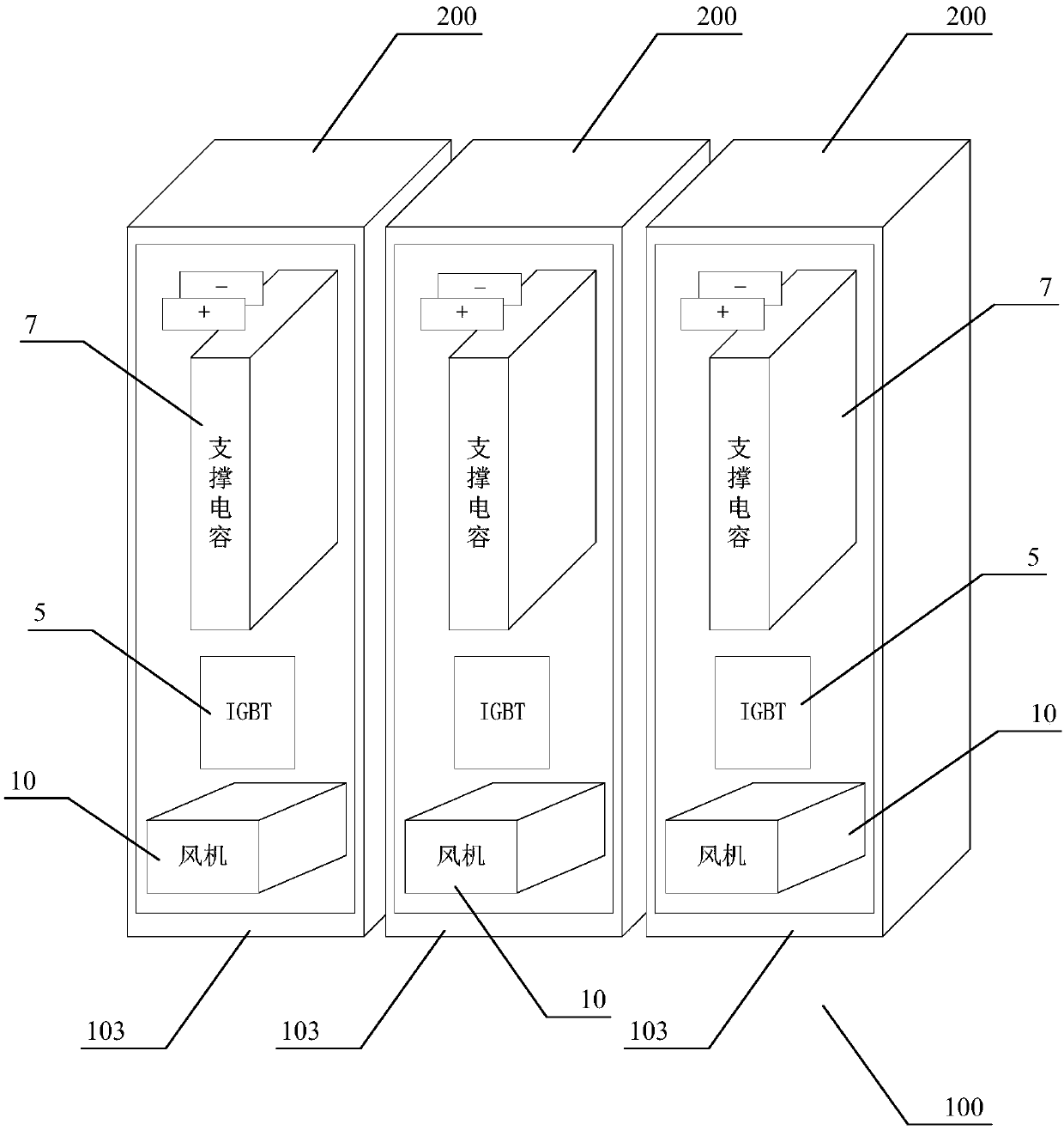
[0061] as attached image 3 , and attached Figure 16 As shown, the embodiment of the third power cabinet specifically includes: three groups of third unit cabinets 103, and the three groups of third unit cabinets 103 all include a cabinet body 200 and a power unit 2 arranged in the cabinet body 200 (using TPM03 type Power unit), pulse control module 3, carrier board 9 and cooling fan 10. The power unit 2 , the pulse control module 3 and the cooling fan 10 all adopt a drawer structure, which are pushed into and fixed on the frame 1 of the cabinet body 200 , and fastened from the outside of the frame 1 . The bearing plate 9 is arranged on the skeleton 1 , the power unit 2 is arranged above the bearing plate 9 , and the fan 10 is arranged at a position corresponding to the power unit 2 under the bearing plate 9 . Two pairs of lower push-in guide rails 11 and upper push-in guide rails 12 are arranged parallel to each other and opposite to each other at the bottom of the carrier...
PUM
 Abstract
Description
Claims
Application Information
 - Generate Ideas
- Intellectual Property
- Life Sciences
- Materials
- Tech Scout
- Unparalleled Data Quality
- Higher Quality Content
- 60% Fewer Hallucinations
Browse by: Latest US Patents, China's latest patents, Technical Efficacy Thesaurus, Application Domain, Technology Topic, Popular Technical Reports.
© 2025 PatSnap. All rights reserved.Legal|Privacy policy|Modern Slavery Act Transparency Statement|Sitemap|About US| Contact US: help@patsnap.com