
Tidal current energy power generation device and using method thereof

A power generation device and tidal current energy technology, which is applied to ocean energy power generation, hydropower generation, engine components, etc., can solve the problems of unutilized tidal current energy, low tidal current power generation efficiency, and limitations, and achieve high vacuum efficiency and improved vacuum efficiency. High power generation efficiency and simple operation

Inactive Publication Date: 2020-05-15
王晖
View PDF7 Cites 2 Cited by
  • Summary
  • Abstract
  • Description
  • Claims
  • Application Information

AI Technical Summary

Problems solved by technology

[0004] The tidal current energy power generation system uses the horizontal flow of seawater to drive the impeller on the hydroelectric generator to rotate and then generate electricity. However, limited by the technology of the hydroelectric generator, it is difficult to drive the generator to generate electricity when the tidal current speed is less than 1.5 m / s. Therefore, most of the tidal current energy has not been utilized, making the power generation efficiency of tidal current energy much lower

Method used


Image

  • Tidal current energy power generation device and using method thereof
  • Tidal current energy power generation device and using method thereof
  • Tidal current energy power generation device and using method thereof

Examples


Embodiment Construction

[0035] The following are specific embodiments of the present invention and in conjunction with the accompanying drawings, the technical solutions of the present invention are further described, but the present invention is not limited to these embodiments.

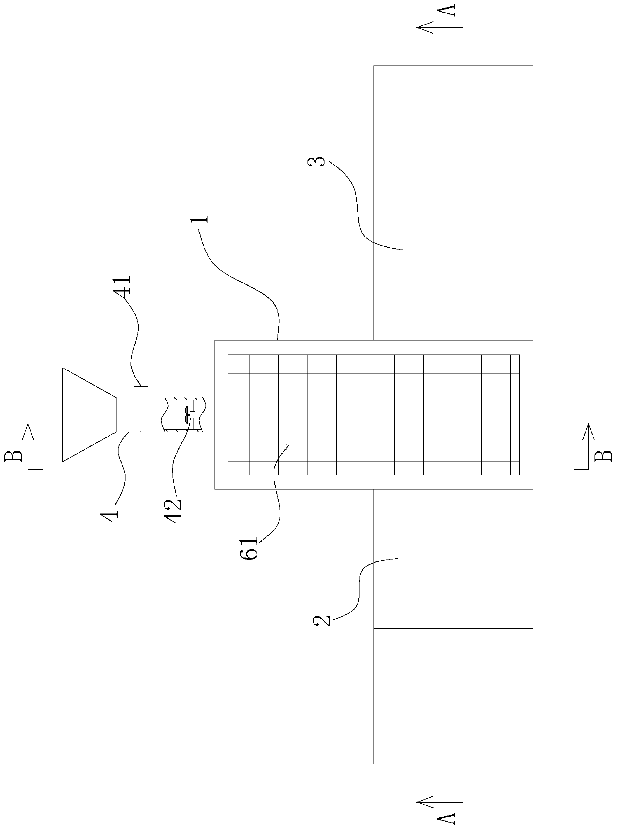
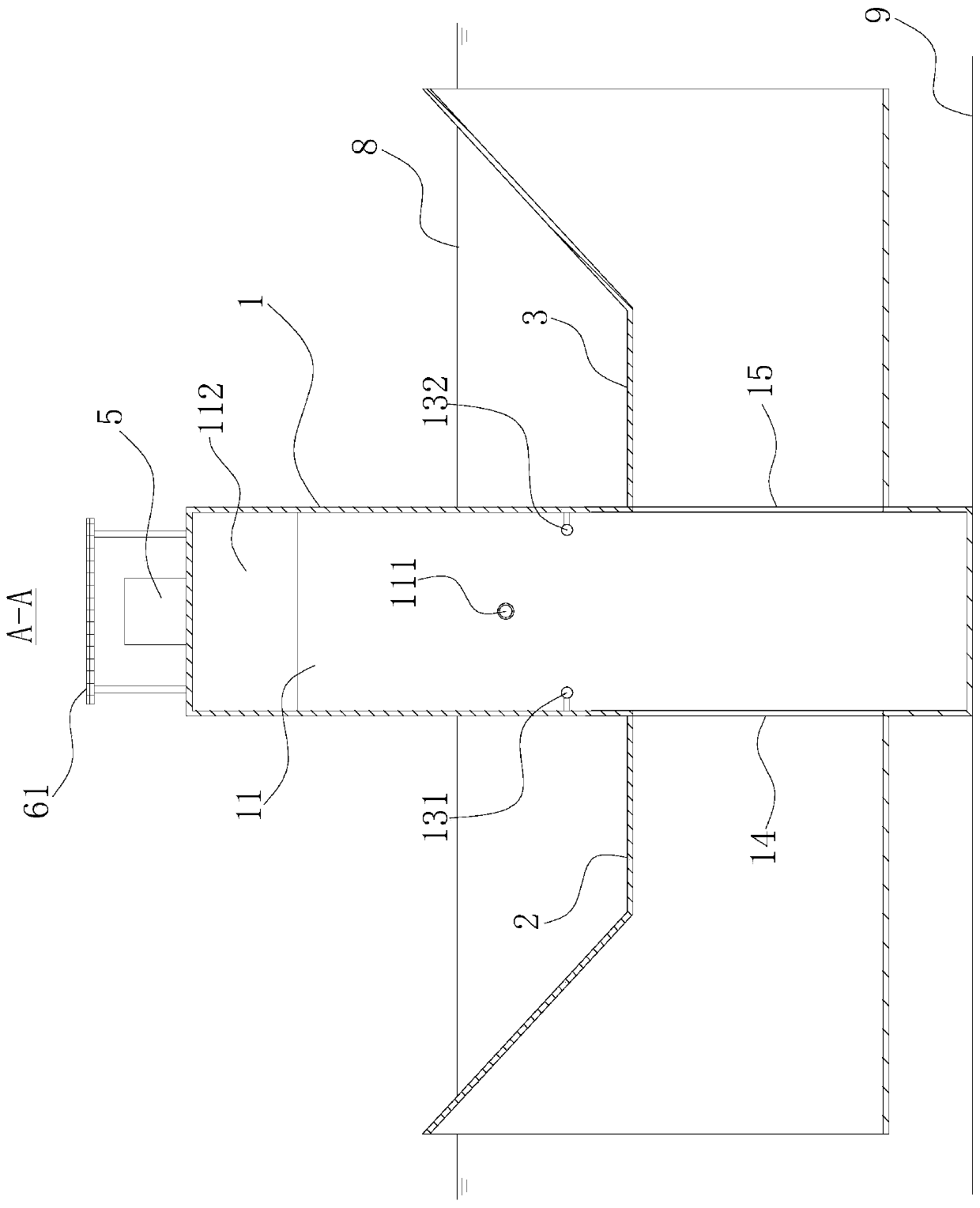
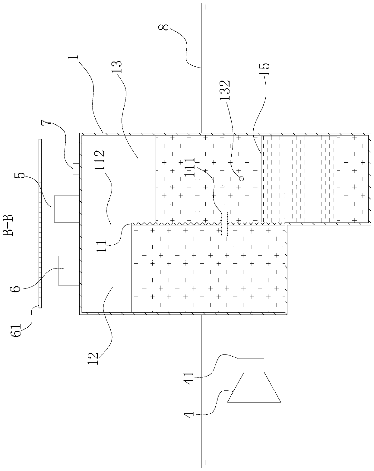
[0036] Such as Figures 1 to 3 As shown, a tidal current energy generating device includes a vacuum water storage tank 1, a first through hole 14, a second through hole 15, a first pipeline 2, a second pipeline 3, a water inlet pipe 4 and a vacuum mechanism.

[0037] The cross-section of the vacuum water storage tank 1 is rectangular, and the vacuum water storage tank 1 is vertically provided with a partition 11, and the partition 11 divides the interior of the vacuum water storage tank 1 into first cavities 12 in sequence from left to right. and the second cavity 13, there is a gap 112 between the upper side of the partition 11 and the top of the vacuum water storage tank 1, and the first cavity 12 and the second cavity 1...


PUM


Abstract

The invention provides a tidal current energy power generation device and a using method thereof, and belongs to the technical field of tidal current energy power generation. The tidal current energypower generation device comprises a vacuum water storage tank, a first channel, a second channel, a first pipeline, a second pipeline, a water inlet pipe and a vacuumizing mechanism, a partition plateis arranged in the vacuum water storage tank and partitions the vacuum water storage tank into a first cavity and a second cavity, the first cavity and the second cavity communicate through a gap, the first channel and the second channel are both formed in the vacuum water storage tank, a first through hole and a second through hole both communicate with the second cavity, the first pipeline is horizontally and fixedly arranged outside the first channel, the second pipeline is horizontally and fixedly arranged outside the second channel, the water inlet pipe is fixedly arranged on the vacuumwater storage tank, provided with a solenoid valve, and internally provided with a water flow power generator, and when the water inlet pipe, the first pipeline and the second pipeline are all completely submerged below the water surface, the vacuumizing mechanism can pump air in the first cavity and the second cavity. Tidal current energy can be fully utilized, and thus the power generation efficiency is improved.

Description

technical field [0001] The invention belongs to the technical field of tidal current energy power generation, and relates to a tidal current energy power generation device and a use method. Background technique [0002] Energy is the lifeblood of a country. As a basic energy source, conventional fossil energy has promoted the development of human civilization, but at the same time it will cause great damage to the natural environment. Global common problems such as the greenhouse effect, environmental degradation and energy shortage are already very serious. [0003] As a kind of green energy, ocean energy has become the object of research and development by countries all over the world because of its advantages such as good renewability, strong predictability, cleanness and environmental protection, and abundant reserves. Tidal current energy is a kind of ocean energy, which refers to the kinetic energy of seawater flow, mainly refers to the relatively stable flow in subm...

Claims


Application Information

Patent Timeline
Patent Type & Authority Applications(China)
IPC IPC(8): F03B13/14F03B13/26F03B11/00
CPCF03B11/00F03B13/14F03B13/26Y02E10/20Y02E10/30
Inventor 王晖
Owner 王晖
Learn More