
Optical diffraction tomography microimaging device and method for depth-of-field tracking

A technology of microscopic imaging and diffraction layer, applied in the field of optical diffraction tomography microscopic imaging, can solve the problem of sample deviation from depth of field, and achieve the effect of improving accuracy and resolution

Pending Publication Date: 2020-05-15
NANJING UNIV +1
View PDF0 Cites 0 Cited by
  • Summary
  • Abstract
  • Description
  • Claims
  • Application Information

AI Technical Summary

Problems solved by technology

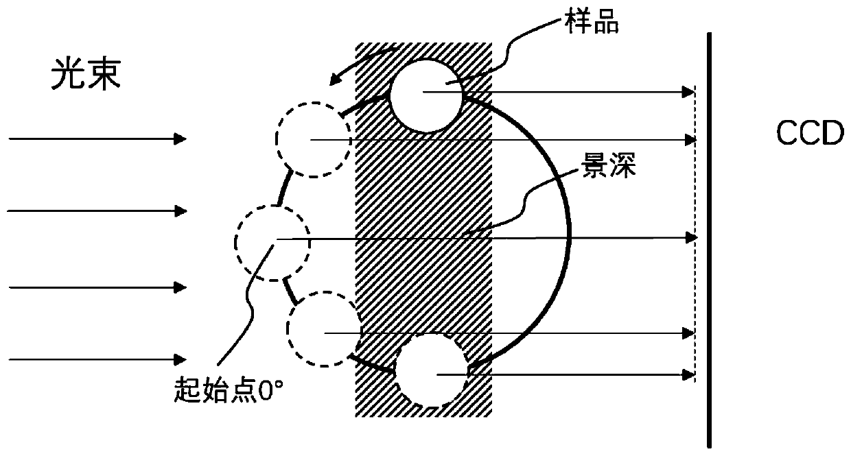
[0004] The present invention provides a depth-of-field tracking optical diffraction tomography microscopic imaging device and method to solve the problem that the sample deviates from the depth of field during the full-angle rotation process in the rotating sample method

Method used


Image

  • Optical diffraction tomography microimaging device and method for depth-of-field tracking
  • Optical diffraction tomography microimaging device and method for depth-of-field tracking
  • Optical diffraction tomography microimaging device and method for depth-of-field tracking

Examples


Embodiment Construction

[0019] Embodiments of the present invention are described in detail below. The embodiments described below with reference to the accompanying drawings are exemplary, and are intended to explain the present invention and should not be construed as limiting the present invention.

[0020] The implementation steps of the optical diffraction tomography microscopy imaging method for depth-of-field tracking of the present invention are as follows

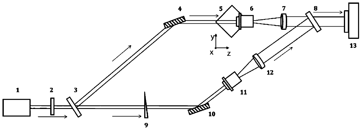
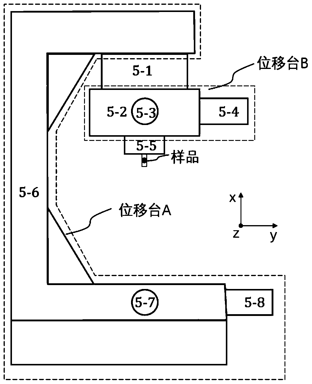
[0021] (1) First, build a depth-of-field tracking optical diffraction tomography imaging device such as figure 1 shown. The imaging system includes: 632.8 nm He-Ne laser 1 with a power of 5 mW; circular graded neutral density filter 2 to adjust the incident light power; 600 lines per mm beam splitter grating 3, which we will pass through the beam splitter grating The first-order diffracted light is used as the object beam, and the zero-order diffracted light is used as the reference beam; the mirror 4 is used to change the propagation d...


PUM


Abstract

The invention provides an optical diffraction tomography microscopic imaging device and method for depth-of-field tracking, and aims to solve the problem that a sample deviates from the depth of fieldin the full-angle rotation process in optical diffraction tomography. And the position of the sample is always kept within the ideal depth of field of the microscope objective through the programmable sample table, so that the quality of the acquired data is optimized while the full-angle projection data is acquired. According to the method, the accuracy and resolution of a sample reconstructionresult in optical diffraction tomography can be improved.

Description

technical field [0001] The invention relates to the technical field of optical diffraction tomography microscopic imaging, in particular to a depth-of-field tracking optical diffraction tomography microscopic imaging device and method. Background technique [0002] Optical Diffraction Tomography (ODT) imaging technology can effectively reconstruct the internal three-dimensional refractive index distribution of biological cells and other microscopic samples, and realize non-invasive and label-free observation of cells and other samples, which is of great significance for biological and medical research. The optical diffraction tomography technology records the scattered field projection data of the sample at different angles by means of the interference of the object beam and the reference beam, and then reconstructs the three-dimensional refractive index information inside the sample according to the optical diffraction tomography algorithm. [0003] In optical diffraction t...

Claims


Application Information

Patent Timeline
Patent Type & Authority Applications(China)
IPC IPC(8): G01N21/41G01N21/47
CPCG01N21/41G01N21/4788
Inventor 王光辉陈家璧吕星曹朔
Owner NANJING UNIV
Learn More