

Design method for low-energy-storage RLC discharge loop to release pulse large current
A discharge circuit and design method technology, applied in the direction of electric pulse generator circuit, energy storage element to generate pulses, etc., can solve the problems of unengineering application, shortening the charging and discharging life of capacitors, and low breakdown field strength
- Summary
- Abstract
- Description
- Claims
- Application Information
AI Technical Summary
Problems solved by technology
Method used
Image

Examples
Embodiment 1
[0059] (Example 1, the theoretical proof that the low energy storage capacitor releases the same or even greater pulse current)
[0060] 1. Introduction to RLC transient discharge circuit.
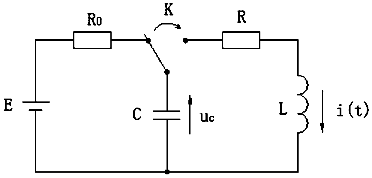
[0061] See figure 1 , figure 1 Is the schematic diagram of the impulse current generator RLC discharge. In the figure, C is the capacitor for energy storage and discharge, L and R are the total inductance and total resistance in the discharge circuit respectively, and K is the reversing switch. When K turns on the charging resistor R 0 , the power supply E charges C to a steady state, at this time there is U C =-E; and when K is connected to L and R in reverse, the voltage on capacitor C discharges to L and R, forming an RLC transient discharge circuit.
[0062] The literature "Circuit Theoretical Basis" ([M]. Chongqing: Communications Corps Engineering College, 1965, Chapter 6 41-43) established the second-order differential equation of the above-mentioned RLC transient discharge cir...
Embodiment 2
[0157] (Embodiment 2, the design method of the discharge circuit of low storage energy RLC discharge pulse large current)
[0158] The design method for releasing the high pulse current of the RLC discharge circuit with low storage energy includes the following steps:
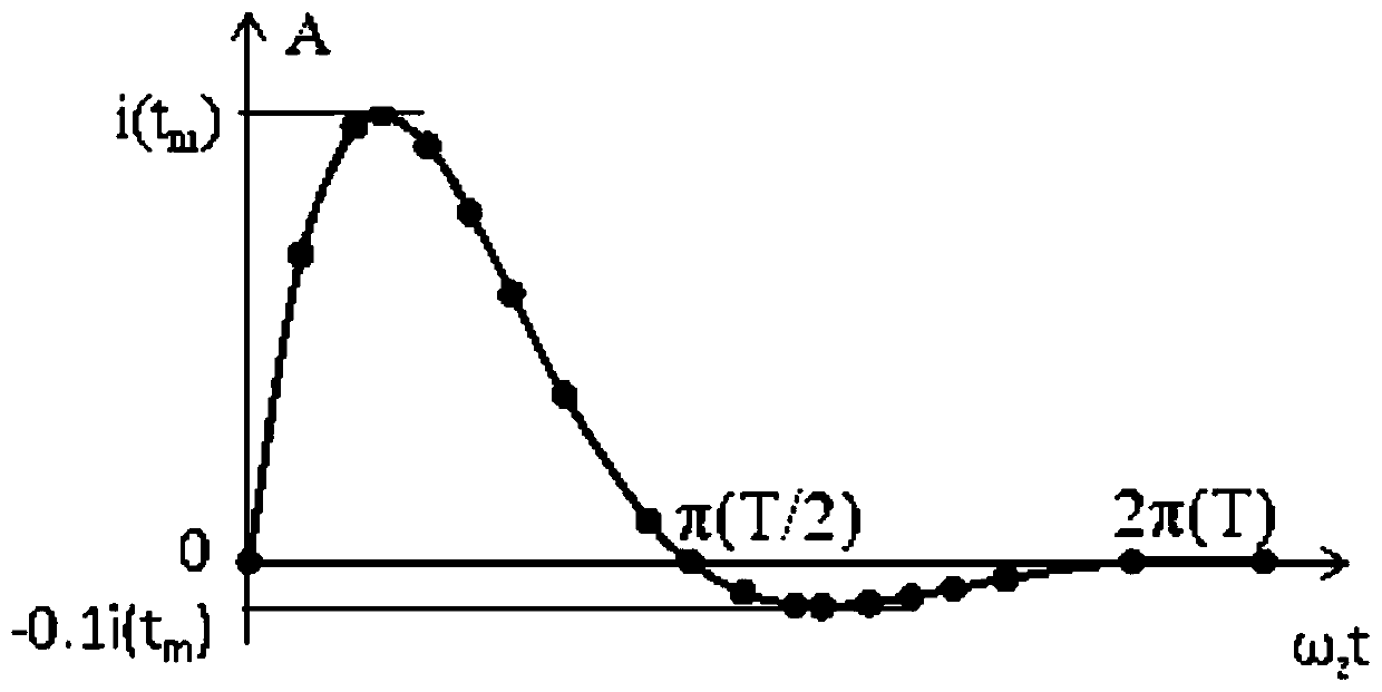
[0159] ① Know the maximum peak current i(t) required by the technical requirements in practical applications m ), and according to the prior art to achieve the maximum peak current i(t m ) E in the designed high energy storage RLC discharge circuit 1 、C 1 , L 1 ;
[0160] The design goal is to solve the E in the low storage energy RLC discharge circuit 2 、C 2 , L 2 , R 2 equal parameter values, guaranteeing that i 2 (t)=i 1 (t), and the damped oscillation period is the same.
[0161] ②Choose to set the E of the low energy storage RLC discharge circuit 2 value, set E 2 1 .
[0162] ③ According to formula (25), get C 2 =E 1 C 1 / E 2 , obviously C 2 >C 1 .
[0163] ④ According to formula (26),...
Embodiment 3
[0167] (Embodiment 3, the design method of the discharge circuit of low storage energy RLC discharge pulse high current)
[0168] The design method for releasing the high pulse current of the RLC discharge circuit with low storage energy includes the following steps:
[0169] ① Know the maximum peak current i(t) required by the technical requirements in practical applications m ), and according to the prior art to achieve the maximum peak current i(t m ) E in the designed high energy storage RLC discharge circuit 1 、C 1 .
[0170] The design goal is to solve the E in the low storage energy RLC discharge circuit 2 、C 2 , L 2 , R 2 equal parameter values, guaranteeing that i 2 (t)=i 1 (t), and the damped oscillation period is the same.
[0171] ②Choose to set the E of the low energy storage RLC discharge circuit 2 value, set E 2 1 .
[0172] ③ According to formula (25), get C 2 =E 1 C 1 / E 2 , obviously C 2 >C 1 .
[0173] ④According to the anti-peak ratio e ...
PUM
 Abstract
Description
Claims
Application Information