Electronic waste treating device and use method thereof

A technology of electronic waste and combustion furnace, which is applied in the direction of furnace control device, waste heat treatment, furnace type, etc., can solve the problems of long time period for microbial treatment, environmental hazards, and difficult treatment, so as to save the pretreatment plant and equipment, The effect of saving initial investment and broad prospects for comprehensive utilization

Pending Publication Date: 2020-05-19
北京保利洁科技发展有限公司
View PDF0 Cites 2 Cited by
  • Summary
  • Abstract
  • Description
  • Claims
  • Application Information

AI Technical Summary

Problems solved by technology

[0005] 2. Mechanical treatment: The dismantling of electronic waste in the process of mechanical treatment is usually manual operation, and the efficiency is low
[0007] 4. Microbial treatment: the part of electronic waste that is easily decomposed by microorganisms is generally very low, and the time period for microbial treatment is long and the efficiency is low
[0012] (4) Insufficient combustion process leads to large fly ash production
The large output of fly ash brings difficulties to the subsequent treatment
[0013] (5) Insufficient combustion process leads to large output of solid slag
[0014] (6) Large air requirement during operation
When mechanical grate incinerators and circulating fluidized bed incinerators are in operation, the air excess coefficient α generally takes a value of 1.6. Due to the obvious excess air, the amount of waste gas generated is large and the treatment cost is high
[0015] (7) High dust content in flue gas
When heavy metal oxides enter the solid slag, the heavy metals in the slag will exceed the standard, which is very harmful to the environment.

Method used


Image

  • Electronic waste treating device and use method thereof
  • Electronic waste treating device and use method thereof

Examples


Embodiment Construction

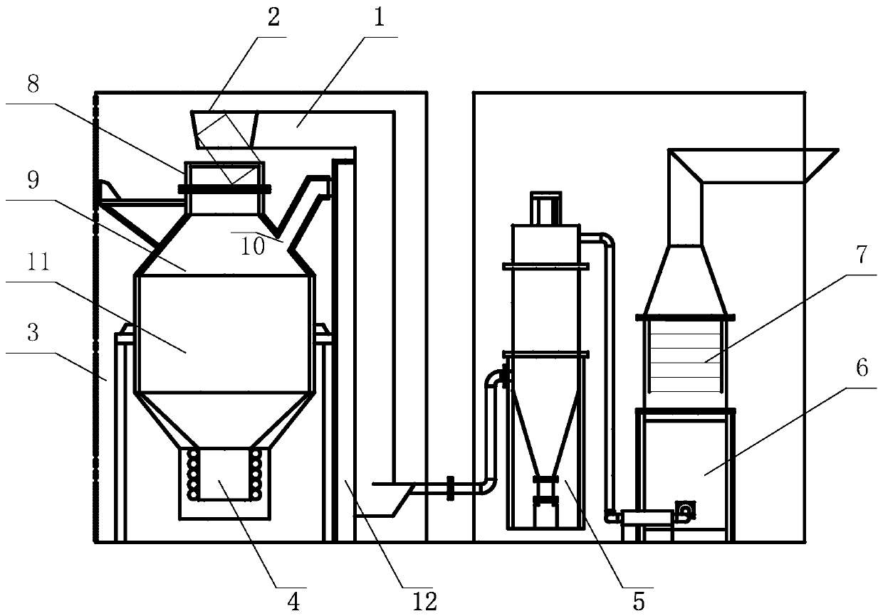
[0053] Attached below figure 1 The device for processing electronic waste and its use method of the present invention will be described in detail.

[0054] A device for processing electronic waste. The device uses a low-carbon direct smelting reduction reactor. The low-carbon direct smelting reduction reactor includes a lift 1, an input tank 2, a furnace body 3, an induction furnace 4, a dust collector 5, Combustion furnace 6 and heat exchanger 7; wherein, the furnace body includes a feed port 8, a feed section 9, a combustible gas outlet 10, and a reduction and melting section 11; the feed port is arranged on the top of the furnace body, the The input tank is fixedly arranged on the feed port; the feed section is connected with the feed port; the combustible gas outlet is provided on the top side of the reduction melting section; the feed section is connected with the reduction melting section; The induction furnace is connected with the reduction melting section; the elevator ...


PUM


Abstract

The invention relates to an electronic waste treating device and a use method thereof. The device comprises a lifter, a feeding groove, a furnace body, an induction furnace, a dust collector, combustion furnaces and a heat exchanger; the furnace body comprises a feeding hole, a feeding section, a combustible gas outlet and a reduction melting section, wherein the feeding hole is formed in the topof the furnace body, the feeding groove is fixedly formed in the feeding hole, the feeding section is connected with the feeding hole, the combustible gas outlet is formed in one side of the top of the reduction melting section, and the feeding section is connected with the reduction melting section; the induction furnace is connected with the reduction melting section; the dust collector is connected with the combustion furnaces and conveys dust to a bag-type dust collector through a fan; and the heat exchanger and the combustion furnaces form an integrated device, and the heat exchanger is arranged above the combustion furnaces. The device has the advantages of being reasonable in structural design, convenient to operate and use and low in maintenance cost, dioxin is not prone to being generated at high temperature, the fly ash yield in the combustion process is small, the waste gas output is effectively reduced, the environment protection is facilitated, and the comprehensive utilization prospect is wide.

Description

Technical field [0001] The present invention relates to the technical field, in particular to a device for processing electronic waste and a method of use thereof. Background technique [0002] E-waste, commonly known as "e-waste", refers to electrical appliances or electronic equipment that are discarded and no longer used, including household appliances such as refrigerators, air conditioners, washing machines, and televisions, as well as obsolete products of computer communication electronic products. The composition of electronic waste is complex, and common hazardous substances include 6 categories: 1. Metal and metal compounds, 2. PVC plastic, 3. Brominated flame retardants, 4. Ink, 5. Phosphate, 6. Phthalate. There are many types of electronic waste, even though the manufacturers of products with the same function vary greatly in material selection, design, and production, they need to be manually separated into printed circuit boards, cables, wires, and picture tubes duri...

Claims


Application Information

Patent Timeline
Patent Type & Authority Applications(China)
IPC IPC(8): F27B19/04F27D17/00F27D19/00F27D21/04
CPCF27B19/04F27D17/004F27D17/008F27D19/00F27D21/04F27D2017/006F27D2019/0087
Inventor 张宝生周军高庆宁
Owner 北京保利洁科技发展有限公司
Why Eureka
Try Eureka