
Liquid cooling heat dissipation assembly for cooling high-voltage motor driver

A high-voltage motor, liquid-cooled heat dissipation technology, applied in cooling/ventilation/heating transformation, electrical components, electrical equipment structural parts, etc., can solve the problems of low heat generation of motor drivers, inability to meet heating power, and poor cooling effect. , to achieve the effect of improving heat dissipation, preventing salt corrosion and prolonging service life

Pending Publication Date: 2020-05-19
HEBEI UNIV OF TECH
View PDF1 Cites 2 Cited by
  • Summary
  • Abstract
  • Description
  • Claims
  • Application Information

AI Technical Summary

Problems solved by technology

The heat dissipation method combined with the heat dissipation structure and the heat dissipation fan has low heat dissipation efficiency; it cannot meet the heat dissipation requirements of high-voltage motor drivers with high heating power of internal electrical components, especially in high-speed and heavy-load environments in ports
[0004] At present, there are few applications for water cooling and heat dissipation inside the high-voltage motor driver. Generally speaking, the heat generation of ordinary motor drivers is not high, and the air-cooled structure alone is enough to ensure that the working temperature is within a safe range; and for port containers. For the high-voltage motor driver on the loading vehicle, the external environment temperature will be very high even in the open air in winter, and it is difficult to meet the heat dissipation requirements by air cooling or air cooling alone, and the cooling effect is poor

Method used


Image

  • Liquid cooling heat dissipation assembly for cooling high-voltage motor driver
  • Liquid cooling heat dissipation assembly for cooling high-voltage motor driver
  • Liquid cooling heat dissipation assembly for cooling high-voltage motor driver

Examples


Embodiment Construction

[0029] The present invention will be further described below in conjunction with the embodiments and accompanying drawings. The specific embodiments are only used to further describe the present invention in detail, and do not limit the protection scope of the claims of the present application.

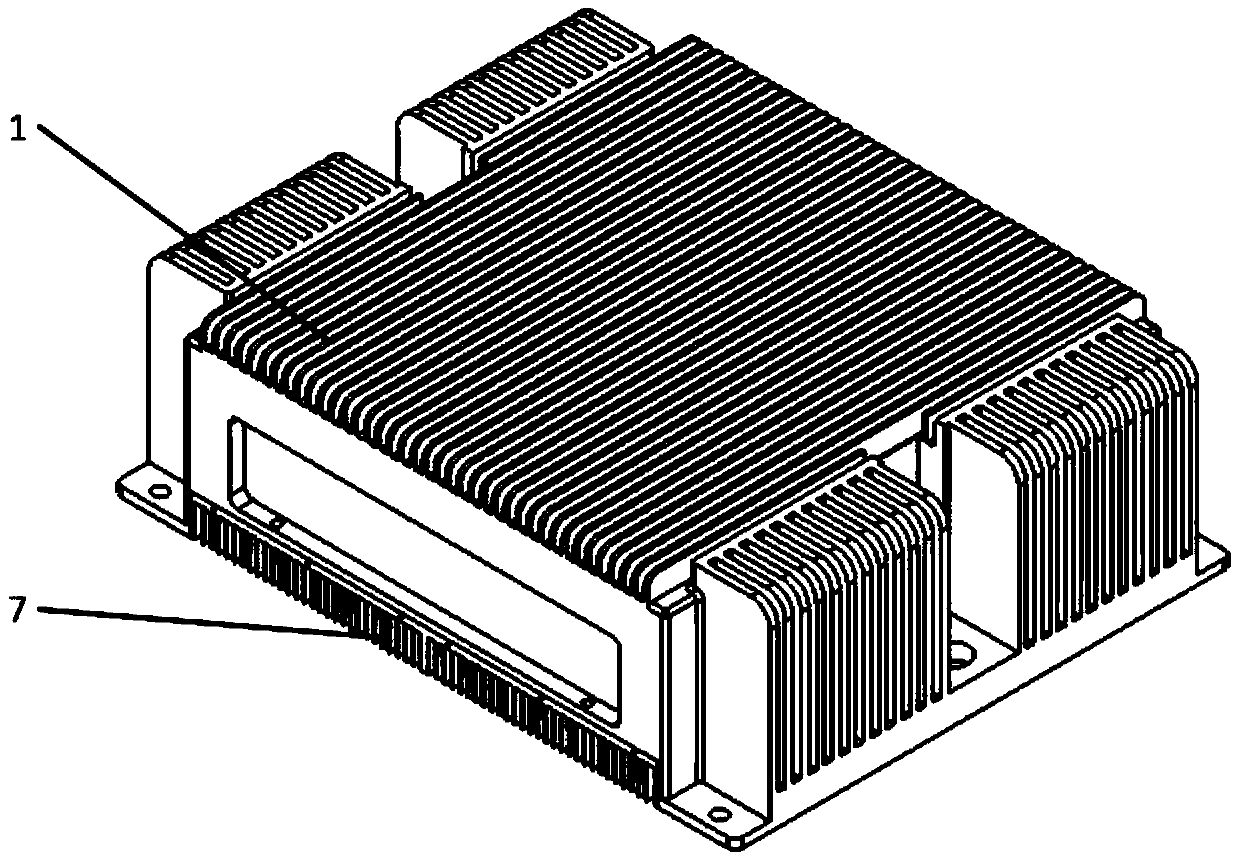
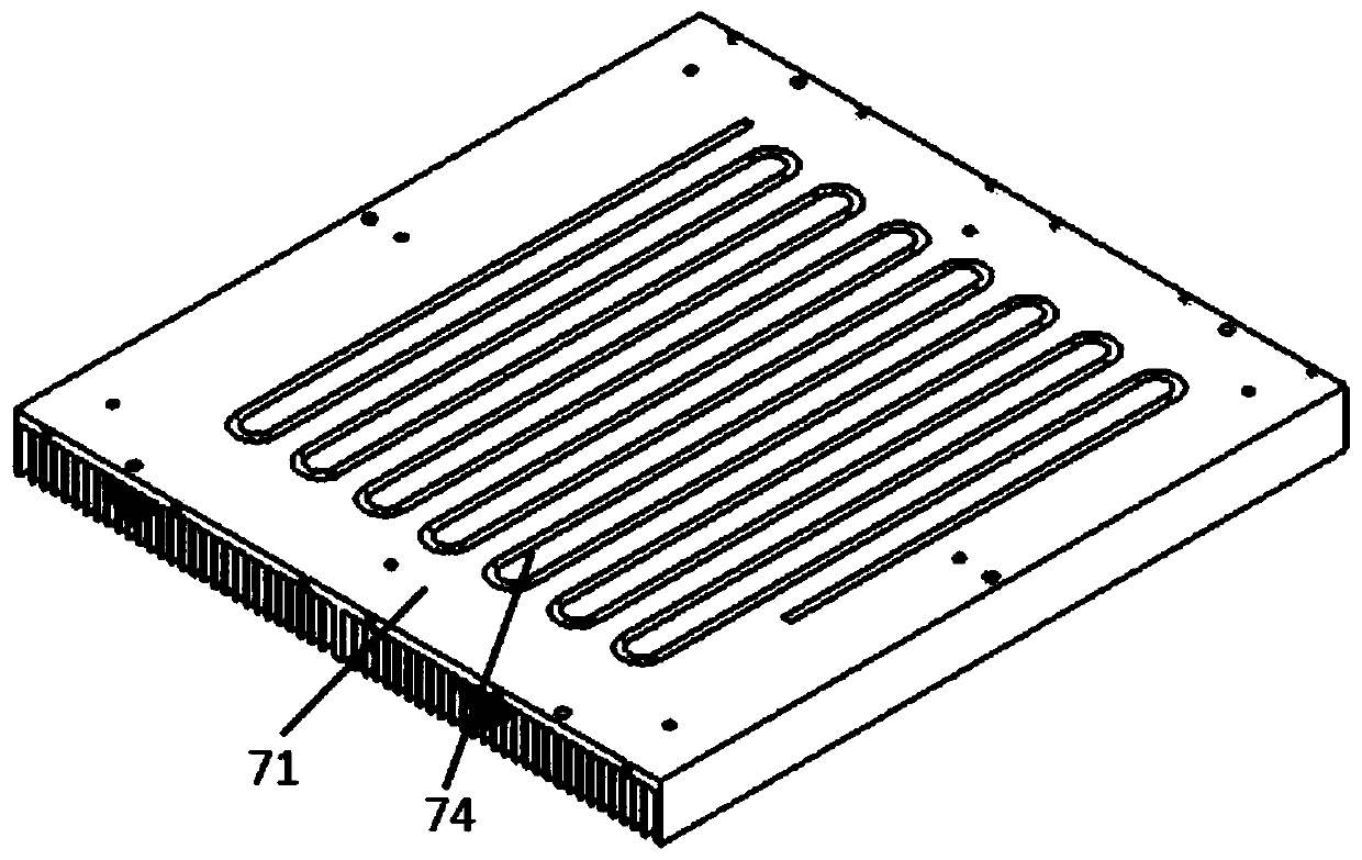
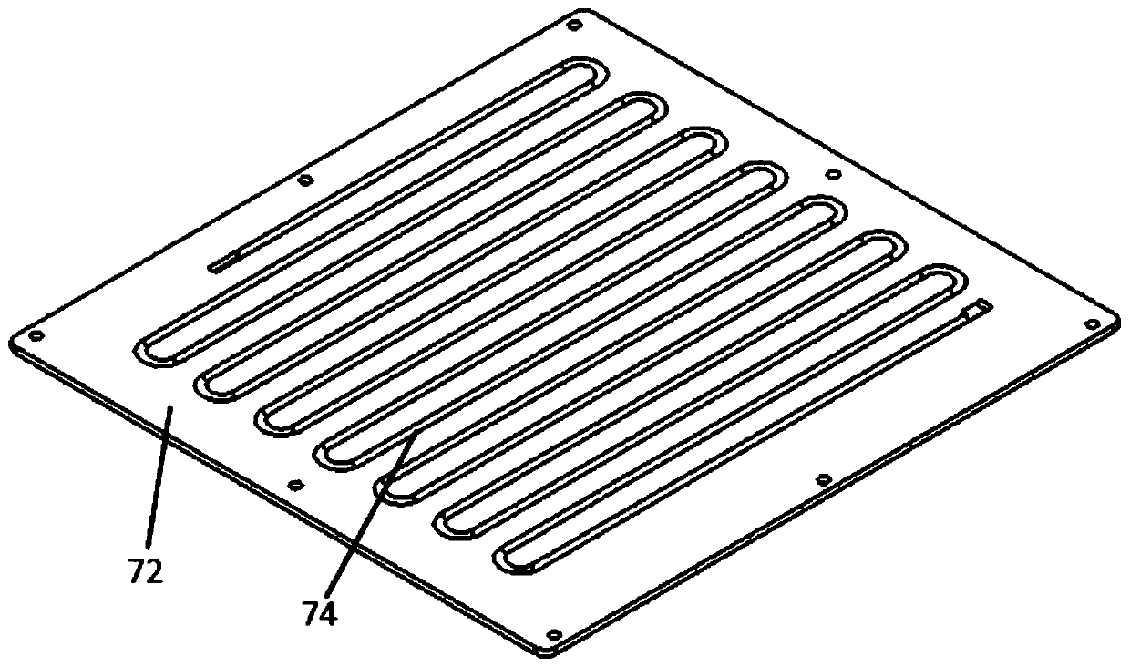
[0030] The present invention provides a liquid-cooled heat dissipation assembly (referred to as heat dissipation assembly, referred to Figure 1-11 ), including a housing 1, a heat dissipation assembly 7, a water channel 6, a circulating water pump 3 and a circulating water pump controller 5, and the heat dissipation assembly 7 includes a heat dissipation fin plate 71, a heat dissipation plate 72 and a serpentine pipe 73;

[0031] The heat dissipation plate 72 is fixed on the heat dissipation fin plate 71, and the bottom of the heat dissipation fin plate 71 is provided with heat dissipation fins; the bottom of the heat dissipation plate 72 and the top of the heat dissipation fin plate...


PUM


Abstract

The invention discloses a liquid cooling heat dissipation assembly for cooling a high-voltage motor driver. The liquid cooling heat dissipation assembly comprises a shell, a heat dissipation assembly,a water channel, a circulating water pump and a circulating water pump controller; and the heat dissipation assembly comprises a heat dissipation fin plate, a heat dissipation plate and a coiled pipe. The heat dissipation plate is fixed to the heat dissipation fin plate, and heat dissipation fins are arranged at the bottom of the heat dissipation fin plate. The coiled pipe is embedded between theheat dissipation plate and the heat dissipation fin plate, and the coiled pipe is filled with a cooling medium; the output end of the circulating water pump is hermetically connected with the inlet of the coiled pipe; the water channel is arranged in the box body of the high-voltage motor driver in an S shape, branch pipes extending to adjacent mounting holes of the box body of the high-voltage motor driver are arranged on the water channel, one branch pipe is connected with the outlet of the coiled pipe, the other branch pipe is connected with the input end of the circulating water pump in asealed mode, and pipe openings of the other branch pipes are sealed through sealing covers. The water channel is filled with a cooling medium. According to the liquid cooling heat dissipation assembly, heat generated in the high-voltage motor driver exchanges heat with the external environment through circular flow of a cooling medium.

Description

technical field [0001] The invention relates to the technical field of motor driver heat dissipation, in particular to a liquid-cooled heat dissipation assembly used for cooling down the temperature of a high-voltage motor driver. Background technique [0002] With the increase of international trade, the demand for heavy-duty automatic transport vehicles in ports is also increasing. In order to improve the efficiency of port transshipment, higher requirements are put forward for the load capacity, motion performance, and reliability of the drive system of the port heavy-duty automatic transport vehicle. The high-voltage motor driver is used as the traction action execution part of the high-speed heavy-duty automatic transport vehicle in the port, and its heat dissipation performance directly affects the transfer efficiency and work stability of the freight vehicle. [0003] The document with the application number 201721170118.4 discloses a servo motor driver. The driver b...

Claims


Application Information

Patent Timeline
IPC IPC(8): H05K7/20
CPCH05K7/20272H05K7/20409
Inventor 张明路周传安刘璇张建华张桐瑞陈浩
Owner HEBEI UNIV OF TECH
Learn More